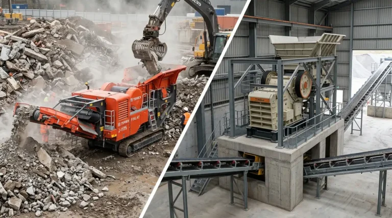


Cone Crusher Structural Analysis: Frame, Main Shaft, Eccentric Sleeve, Mantle, and Concave
What You Will Learn from This Guide
A cone crusher’s crushing action comes from five parts working together: the frame, the main shaft, the eccentric sleeve, the mantle, and the concave. This guide walks through what each part does on its own. It then shows how they connect into one working system, since no single part explains the crusher’s motion by itself. It serves an engineer or technician who wants to understand cone crusher construction at a structural level, and after reading, you will be able to trace how rotary motor power becomes the gyrating crushing action inside the chamber.
The Frame: Two Parts, One Structure
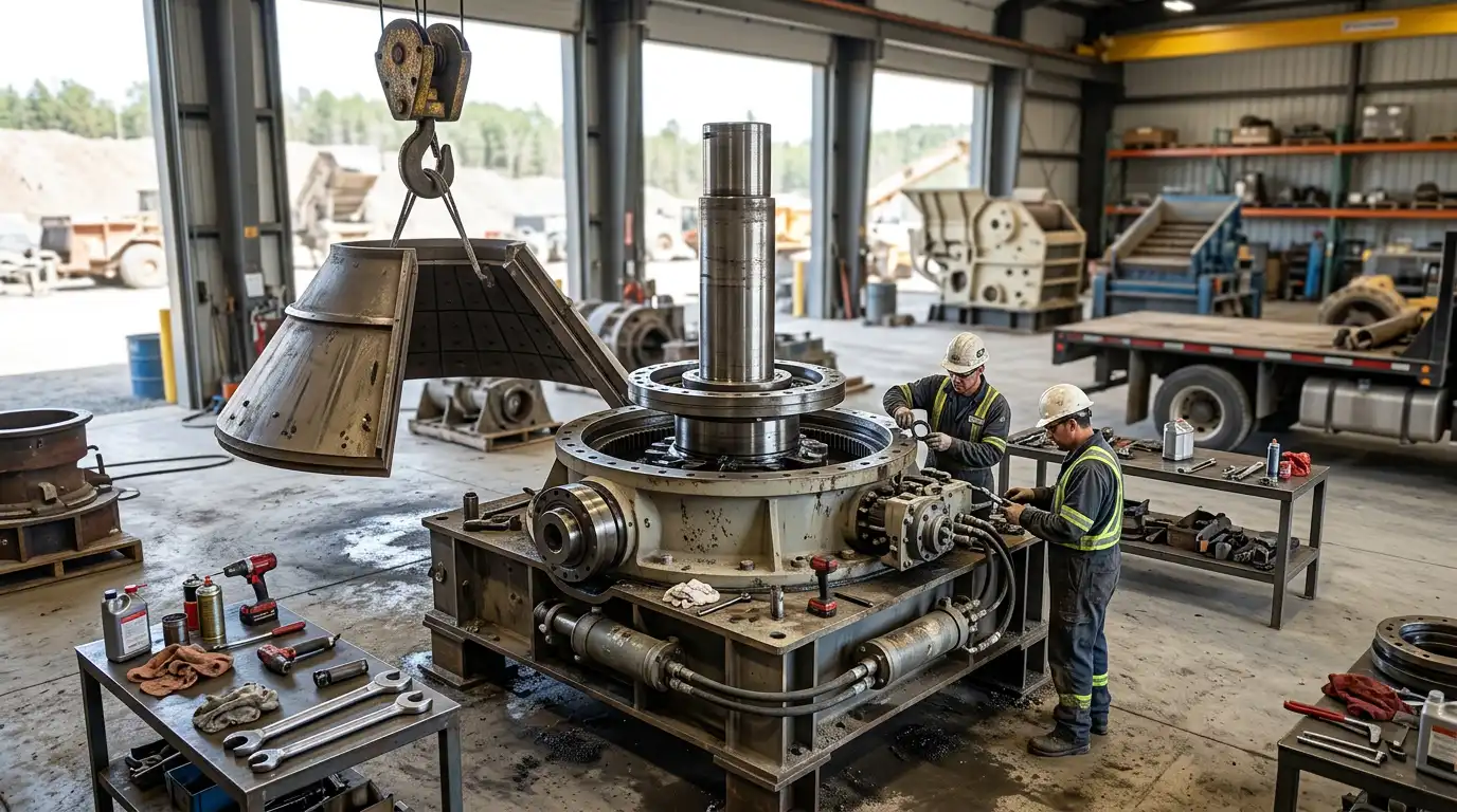
A cone crusher frame splits into two main sections. The lower frame houses the eccentric sleeve and the drive mechanism, including the countershaft that brings power in from the motor. The upper frame houses the concave and the adjustment ring above it.
The frame’s job goes beyond just holding parts in place. Every crushing force generated inside the chamber passes through the frame on its way to the foundation. A frame has to absorb that repeated, cyclical load without flexing enough to throw off the precision the crushing chamber depends on.
The Main Shaft: Gyrating, Not Spinning
The main shaft runs from the bottom of the machine, where it engages the eccentric sleeve, to the top, where the mantle is mounted. It is easy to assume the shaft spins on its own axis the way a motor shaft does. That assumption is not quite right.
The shaft’s actual motion is gyration, not rotation on a fixed centerline. Its axis traces a small cone shape as the eccentric sleeve pushes it around. Some designs do allow the shaft to slowly rotate as well, a slight creeping motion driven by friction rather than the drive train itself. That slow creep helps even out wear around the mantle’s full circumference, but it is a secondary effect. The gyration is what actually crushes rock.
The Eccentric Sleeve: Where Rotation Becomes Gyration
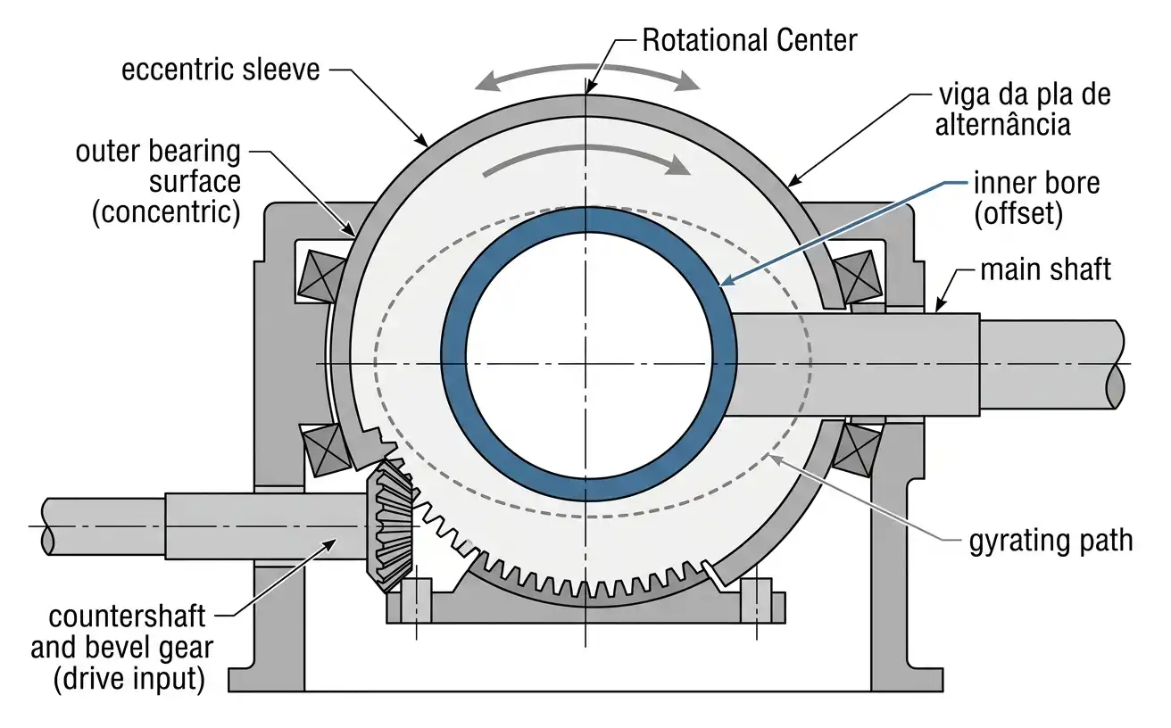
The eccentric sleeve is the single component that makes a cone crusher work the way it does. Its outer surface rotates within the frame, driven by a bevel gear meshing with the horizontal countershaft. That countershaft connects back to the motor through a pulley or direct coupling.
The sleeve’s inner bore is where the real trick happens. It is offset from the sleeve’s rotational center, not aligned with it. The main shaft passes through that offset bore.
As the sleeve rotates around its own true center, the offset bore drags the main shaft around in a circle. The shaft cannot stay still.
That offset distance is called the throw, and it sets how far the mantle swings at any point in the chamber. A larger throw means a more aggressive stroke and generally higher capacity. Some designs let an operator change the throw by installing a different eccentric bushing size, adjusting the crusher’s behavior without changing the whole assembly.
Eccentric sleeve construction varies by design generation. Older and simpler designs use a sliding bronze bushing arrangement between the sleeve and the frame, and between the sleeve and the main shaft. Sliding friction limits how fast that arrangement can safely run. Newer designs replace some or all of those sliding surfaces with rolling bearings, cutting friction and allowing higher operating speed for the same component sizes.
The Moving Cone (Mantle): Compression That Travels Around the Circumference
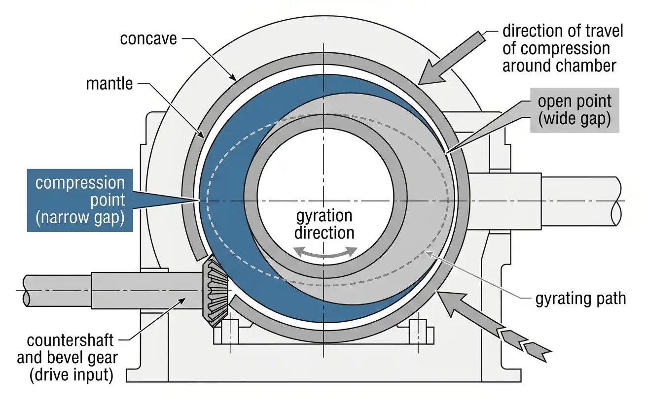
The mantle mounts at the top of the main shaft and gyrates along with it. Because the shaft’s axis traces that small cone shape, the mantle’s outer surface does not move uniformly toward or away from the concave. It moves closer on one side of the chamber while moving farther away on the opposite side, at the same instant.
This is the actual crushing mechanism, and it is different from how it might first appear. There is no single moment where the whole chamber closes at once. Instead, a point of maximum compression travels continuously around the circumference as the shaft gyrates. It squeezes rock at whichever point currently sits closest to the concave.
The Fixed Cone (Concave): The Stationary Partner
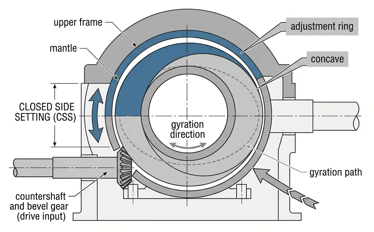
The concave sits in the upper frame, held by the adjustment ring above it. Unlike the mantle, the concave does not gyrate. It stays fixed relative to the frame during normal operation.
Its inner surface is shaped to pair with the mantle’s outer surface. Together the two surfaces define the crushing chamber’s profile from top to bottom.
Adjusting the closed side setting means moving the concave’s effective position relative to the mantle. Mechanically adjusted designs do this by rotating the adjustment ring on threads. Hydraulically adjusted designs shift it vertically instead.
How the Five Parts Work as One System
Following the path from motor to finished product ties these five parts together. Power enters through the countershaft, turning the eccentric sleeve’s bevel gear. The sleeve’s offset bore forces the main shaft into a gyrating path rather than letting it spin freely.
The mantle is fixed to the top of that shaft and gyrates with it. One side of the chamber moves into compression against the concave while the opposite side opens to accept new material. The frame absorbs the reaction force from every one of those compressions and carries it down into the foundation.
Each part depends on the others doing their job correctly. A worn eccentric bushing changes the throw the whole system was designed around. A cracked frame section changes how precisely the mantle and concave stay aligned. Understanding this chain helps trace a symptom, like uneven wear or unexpected vibration, back to the specific component actually responsible.
Frequently Asked Questions
Does the main shaft in a cone crusher spin on its own axis?
Not primarily. The shaft’s main motion is gyration, tracing a small cone shape as the eccentric sleeve pushes it around. Some designs allow a slow secondary rotation driven by friction, which helps even out wear, but the gyration itself is what actually crushes material.
What does the eccentric sleeve’s throw actually control?
The throw is the offset distance between the eccentric sleeve’s outer rotational center and its inner bore. It sets how far the mantle swings at any point in the chamber. A larger throw produces a more aggressive stroke and generally higher capacity, and some designs let an operator change it by swapping the eccentric bushing.
Why doesn’t the whole crushing chamber close at the same time?
Because the mantle gyrates rather than moving straight in and out, only one point around the chamber’s circumference reaches maximum compression at any given instant. That compression point travels continuously around the chamber as the shaft gyrates, rather than the whole gap closing uniformly.
What is the difference between the mantle and the concave?
The mantle is the moving cone, mounted on the main shaft and gyrating with it. The concave is the fixed cone, held in the upper frame and stationary during normal operation. Their two surfaces together define the crushing chamber, and CSS adjustment works by changing the concave’s position relative to the mantle.