

Ball Mill Installation Guide: Foundation, Alignment, and Grouting
What You Will Learn from This Guide
A ball mill’s foundation, alignment, and grouting are one interconnected sequence, not three separate tasks. This guide covers how the foundation is designed for dynamic load, why trunnion bearing sole plates are deliberately crowned rather than flat, and why grouting happens in stages tied to what has already been verified. It serves an installation engineer or project manager overseeing a ball mill installation, and after reading, you will understand why the order of these steps matters as much as any single step done well in isolation.
Foundation: Designed for Dynamic, Not Static, Load
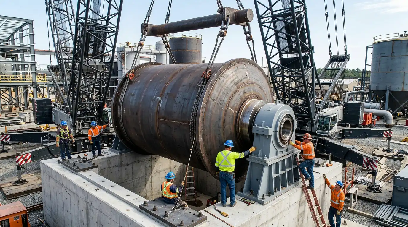
A ball mill foundation carries a fundamentally different load profile than most plant equipment. The shell, liners, grinding media, and material inside it together represent a massive static mass. That mass rotates continuously, adding a dynamic load component a static foundation design does not need to handle.
Foundation design for this kind of equipment follows dynamic-load engineering principles. It does not use the static bearing-capacity calculations built for a simple equipment pad. Soil investigation, reinforcement detailing, and anchor bolt placement all account for the sustained vibration and rotating mass the foundation carries for the mill’s operating life, not just its dead weight at rest.
Anchor bolts and bolt pipes need careful placement before the concrete pour. Concrete intruding into these pipes limits how bolts can be positioned during erection. Forms need enough reinforcement to resist swelling during the pour, particularly where the final clearance tolerance is tight.
Trunnion Bearing Sole Plates: Crowned, Not Flat
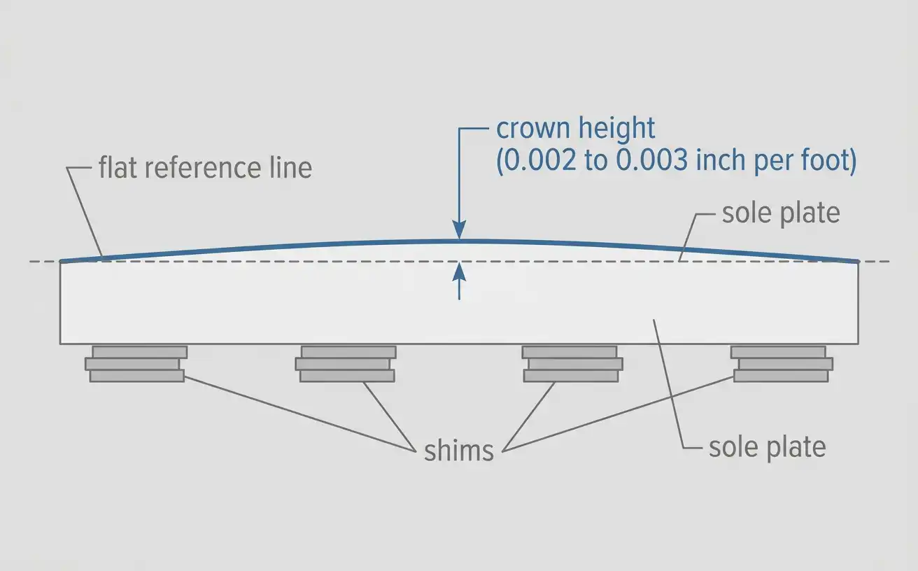
Trunnion bearing sole plates are installed on shims with a deliberate crown, not set perfectly flat. The plate sits slightly higher at the center than at the ends, typically by roughly 0.002 to 0.003 inch per foot of sole plate length.
This crown exists for a specific reason. A flat plate deflects under the sustained weight and dynamic load of the rotating shell over time. Building in a slight upward crown means the plate settles toward flat under real operating load, rather than starting flat and sagging concave. A sole plate installed dead flat will not stay flat once the mill is running.
Centerlines and elevation reference points get scribed onto permanent fixtures before the sole plates go in. This establishes the datum every later alignment step measures against. That reference work happens once, early, and every subsequent check ties back to it.
Staged Grouting: What Gets Grouted First, and What Waits
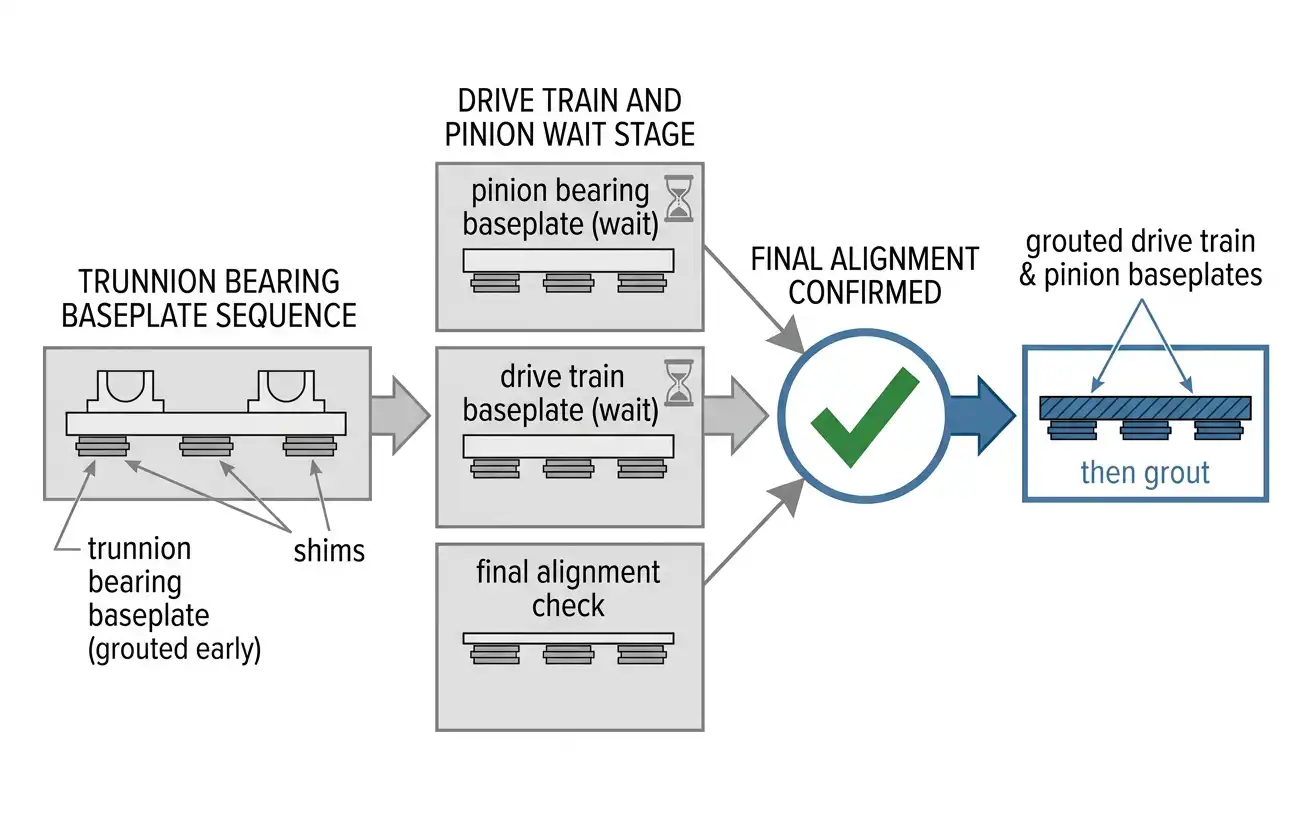
Grouting is not one step performed once at the end of installation. It happens in stages, and the sequence matters. Trunnion bearing baseplates are grouted relatively early, once they are shimmed, crowned, and confirmed to specification. They establish the fixed reference the rest of the drive train aligns against.
The pinion bearing baseplate and the drive train baseplates, including the gearbox and motor, are deliberately left un-grouted at this stage. They stay on shims, adjustable. Meanwhile the shell is lowered into the trunnion bearings, the girth gear is installed, and radial and axial alignment is checked and corrected.
Grouting the drive train only happens after final alignment is confirmed, not before. Grouting something still being adjusted defeats the purpose of grouting. Once cured, grout locks a component’s position permanently enough that correcting a later alignment error means breaking that grout out and starting over.
Girth Gear and Pinion Alignment
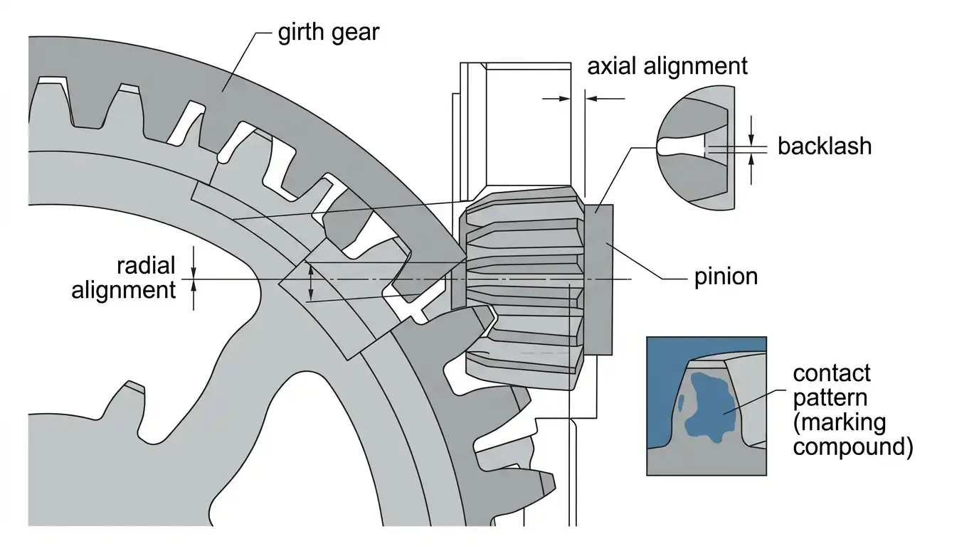
The girth gear mounted to the mill shell and the pinion driven by the motor and gearbox need to mesh correctly. This has to hold across the gear’s full rotation, not just at one measured point. Runout on the girth gear mounting flange gets measured before the gear goes on. A flange that is not true carries that error into every subsequent alignment check.
Radial and axial alignment between girth gear and pinion get checked using shims under the pinion bearing pedestal. Small shim adjustments move the pinion in small increments. The goal is backlash and root clearance falling within the tolerance the mill manufacturer specifies for that gear module.
Contact pattern verification typically uses a marking compound applied to the gear teeth. This confirms the two gears are actually meshing across the intended area of the tooth face, not just close enough on paper.
A no-load test run follows alignment, before the mill sees any load. This run checks vibration, noise, and bearing temperature with the drive train confirmed correct. It serves the same diagnostic purpose described in this project’s jaw crusher commissioning guide: isolating mechanical problems from anything related to feed or load.
Grouting Material and Surface Preparation
Epoxy grout, rather than standard cementitious grout, is the specified material for this kind of precision rotating equipment in most current installation practice. Epoxy grout provides higher compressive strength and better vibration resistance. It also forms a stronger chemical bond to properly prepared concrete than cementitious alternatives offer.
Surface preparation before grouting matters as much as the grout material itself. The concrete surface needs to be roughened and completely free of oil, solvent, or grease residue. Any contamination on that surface prevents the chemical bond the grout depends on for proper load transfer. A grout pour onto an inadequately prepared surface can look complete while never actually bonding to the foundation underneath it.
Grout’s job, once cured, is uniform load transfer from the equipment base into the foundation. Machine bases and concrete surfaces both have enough surface irregularity that setting a baseplate directly on bare concrete creates point loads. Concrete alone was never designed to carry those loads.
A Practical Installation Sequence Checklist
- Foundation designed and poured to dynamic-load specifications, with anchor bolt pipes correctly placed before the pour.
- Centerlines and elevation reference points scribed onto permanent fixtures before sole plate installation.
- Trunnion bearing sole plates shimmed and crowned to specification, then grouted.
- Pinion bearing and drive train baseplates left un-grouted, on shims, through shell installation and girth gear alignment.
- Girth gear runout measured before installation, then radial and axial alignment confirmed against backlash, root clearance, and contact pattern criteria.
- Drive train baseplates grouted only after final alignment is confirmed correct.
- No-load test run completed and reviewed before introducing feed material.
Consequences of Getting This Wrong
A sole plate installed flat instead of crowned settles concave over time. This works alignment out of tolerance months after commissioning, rather than immediately. This kind of failure is expensive precisely because it does not show up on day one, when it would still be easy to fix.
Grouting the drive train before alignment is finalized creates the opposite problem. Any correction discovered afterward requires breaking out cured grout. That intervention costs far more in time and money than the extra patience of grouting in the correct order would have.
Frequently Asked Questions
Why are trunnion bearing sole plates installed with a crown instead of flat?
A flat sole plate deflects under the sustained weight and dynamic load of the rotating shell over time, sagging concave. A slight upward crown, typically 0.002 to 0.003 inch per foot of plate length, changes that outcome. The plate settles toward flat under real operating load, instead of starting flat and getting worse.
Why isn’t the drive train grouted at the same time as the trunnion bearings?
The trunnion bearings establish a fixed reference the rest of the drive train aligns against, so they can be grouted once confirmed correct. The pinion bearing and drive train baseplates stay adjustable on shims until girth gear alignment is fully verified. Grouting locks their position and makes later correction far more disruptive.
Why does this guide recommend epoxy grout over standard cementitious grout?
Epoxy grout offers higher compressive strength, better vibration resistance, and a stronger bond to properly prepared concrete. This matters for equipment carrying continuous dynamic load, like a rotating ball mill shell. It is standard practice for precision rotating equipment in current industry installation guidance.
What happens if the concrete surface isn’t properly prepared before grouting?
Oil, solvent, or grease residue on the concrete surface prevents the chemical bond the grout depends on for load transfer. A grout pour can look complete on the surface while never actually bonding to the foundation underneath. That defeats the purpose of using grout at all.
References and Sources
- American Concrete Institute — ACI 351.3R-18: Report on Foundations for Dynamic Equipment
- American Concrete Institute — ACI 351.1R-12: Report on Grouting between Foundations and Bases for Support of Equipment and Machinery
- American Petroleum Institute — API RP 686: Recommended Practice for Machinery Installation and Installation Design