

Raymond Mill System Composition: Main Mill, Fan, Classifier, Dust Collection, and Feeding
What You Will Learn from This Guide
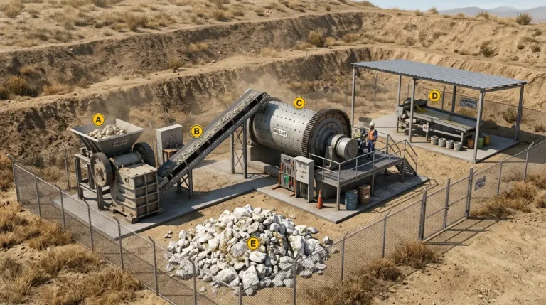
A Raymond mill is not one machine. It is five subsystems working as a matched set: the main mill, the fan, the classifier, dust collection, and feeding. This guide explains what each subsystem does. More importantly, it explains how they must be sized together, not chosen one at a time. It serves an engineer or buyer specifying a complete Raymond mill line, and after reading, you will be able to spot a mismatch between subsystems before it becomes a commissioning problem.
Overview
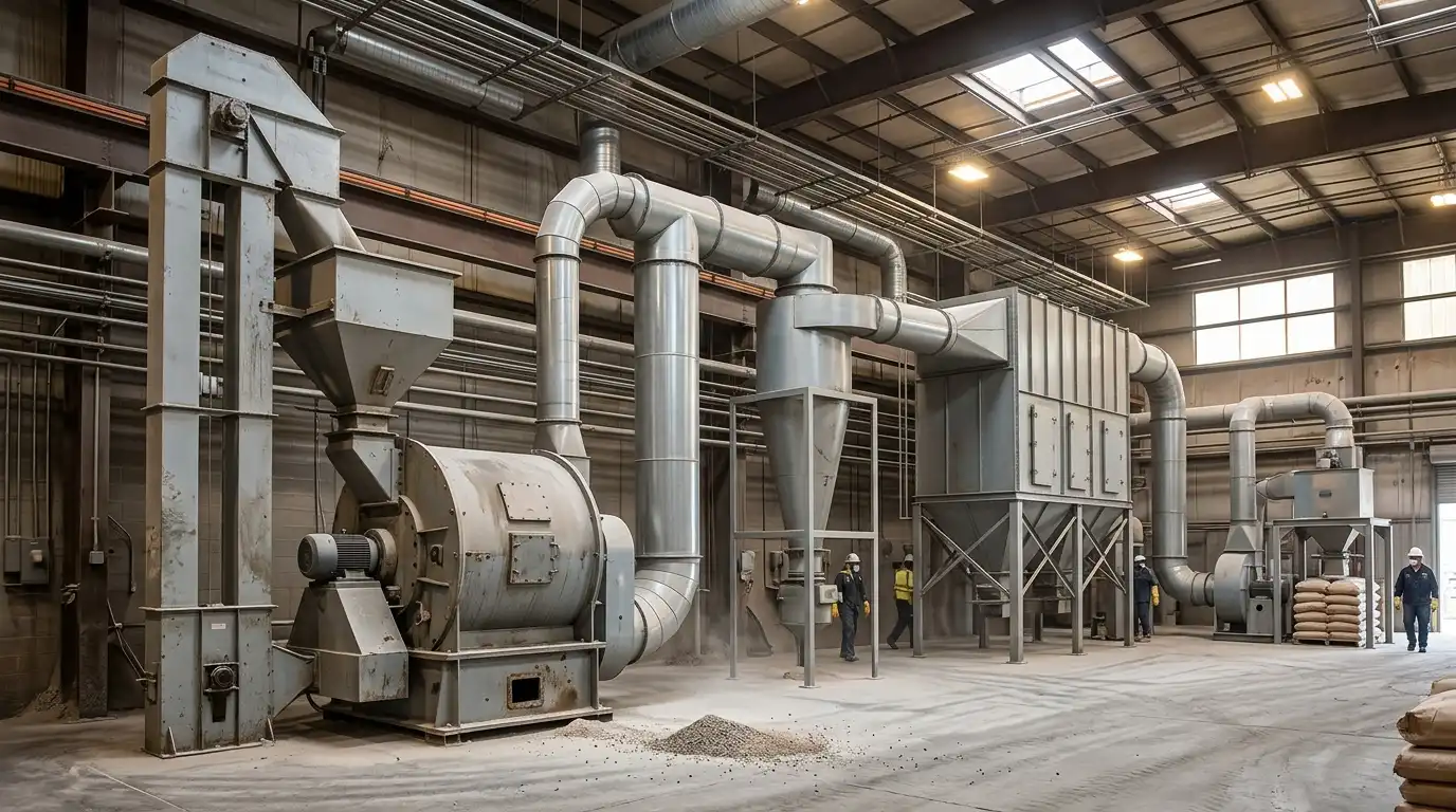
Most buyers evaluate a Raymond mill by its main grinding unit alone. That unit only works inside a closed airflow loop. The loop includes a fan, a classifier, a dust collection stage, and a feeding system. Each piece depends on the others.
A fan sized for one mill model will not move enough air for a larger one. A classifier tuned for a coarse cut will not hold a fine one if the fan cannot supply the right air velocity. A feeder running faster than the mill and fan can process will overload the whole loop. This guide treats the five subsystems as one system. That is how they actually have to be specified.
The Main Mill
The main mill is where size reduction happens. A grinding roller presses against a grinding ring under centrifugal force, driven by a rotating spider assembly. This guide does not re-derive that mechanism in detail. A companion guide on how a Raymond mill works covers the roller, ring, and pendulum suspension structure specifically, for readers who want that mechanical depth.
What matters here is the main mill’s output. It sets the air volume the fan must move. It also sets the particle load the classifier and dust collector must handle downstream. A larger frame size does not just grind more material. It demands a proportionally larger fan, classifier, and collection system too.
The Fan
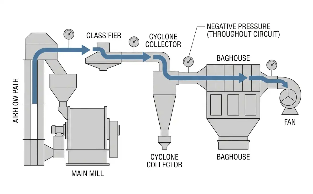
The fan is the engine of the whole system. It pulls air through the mill, up to the classifier, through the cyclone collector, and into the baghouse, then exhausts it.
This single airflow does three jobs at once. It carries ground powder to the classifier. It carries fine powder onward to collection. It holds the entire circuit under negative pressure.
Fan power scales with frame size for a real reason, not just a pricing convention. A larger mill produces more airborne powder per minute. Moving that volume through the same ductwork and filter area needs proportionally more fan power.
On the MGW series, fan motor rating runs from 55 kW on the smallest frame to 315 kW on the largest. It tracks main mill motor power closely across the range.
An undersized fan cannot maintain negative pressure at the mill housing. That risks dust escaping into the work area instead of following the intended airflow path. An oversized fan wastes energy. It can also disrupt the classifier’s cut point, since classification depends on air velocity through the chamber, not just raw airflow volume.
The Classifier
The classifier sorts ground material by size before it leaves the grinding loop. A rotating cage or vane wheel lets fine particles pass through. Coarse particles get rejected back into the grinding chamber for another pass. This closed loop is what lets a Raymond mill hold a consistent fineness target, instead of producing an uncontrolled size spread.
Classifier speed sets the cut point. Air velocity through the classifier chamber sets how sharp that cut actually is. The same classifier speed produces a different result at a different air velocity. That is why the classifier cannot be evaluated separately from the fan it is paired with.
Finer fineness targets need higher classifier speed. This generally reduces net throughput. At a tighter cut, the classifier rejects a larger share of material back for regrinding.
Dust Collection
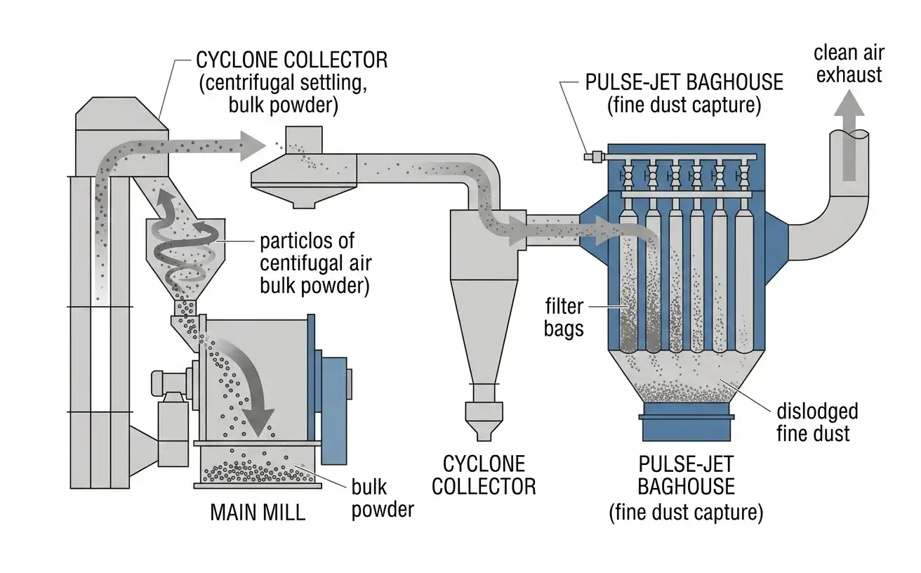
Dust collection runs in two stages, not one. The cyclone collector comes first. It removes the bulk of the powder from the airstream by centrifugal settling.
This is the finished product stream in a Raymond mill system, not waste. Cyclone efficiency directly affects how much saleable powder the plant actually recovers.
The pulse-jet baghouse comes second. It captures the finer dust the cyclone cannot settle out, before the air exhausts.
Splitting the load this way protects the baghouse. Sending raw, unclassified airflow straight to a baghouse would load the filter bags far faster. That shortens their service life. A properly matched two-stage system keeps the baghouse handling only the fine fraction it is actually designed for.
Maintaining negative pressure across this entire path is not a housekeeping detail. It keeps dust contained within the equipment, rather than escaping into the work environment. That is the same principle industrial ventilation guidance for mineral processing operations is built around.
Feeding
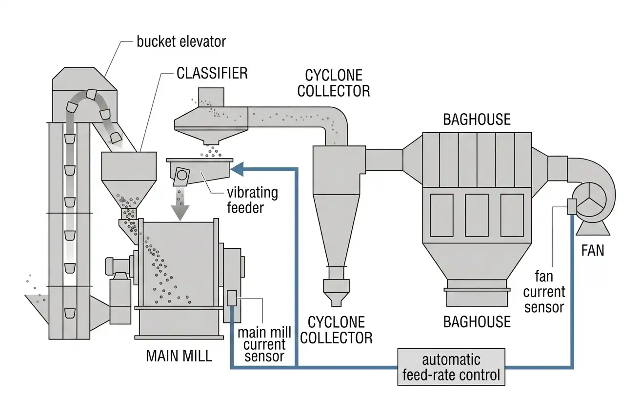
The feeding stage controls how fast material enters the loop the other four subsystems have to process. A bucket elevator lifts pre-crushed feed to a hopper above the mill. A vibrating feeder then meters it into the grinding chamber at a controlled, continuous rate.
That word “controlled” matters more than it sounds. On a properly specified system, the feeder is interlocked with the main mill and fan.
Feed rate gets adjusted automatically, based on motor current readings from both. This keeps the feeder from loading the mill faster than the stages downstream can process. That is a system-level failure mode, not a feeder problem in isolation.
How the Five Subsystems Interact
A mismatch anywhere in this loop shows up somewhere else, not necessarily at its source. An undersized fan starves the classifier of the air velocity it needs. That can show up as an off-spec fineness result. It looks like a classifier problem, but it is actually a fan sizing problem.
A feeder running without current-based interlock can overload the mill. The classifier and collection stages downstream cannot keep pace.
The result is dust breakthrough at the baghouse. It looks like a filter problem, but it traces back to feed control. Diagnosing these issues correctly means checking the whole loop, not just the subsystem where the symptom appears.
Applications by Industry
Non-metallic mineral processing is where this five-subsystem architecture matters most. Materials like barite, calcite, limestone, and bentonite all pass through the same feeding, grinding, classification, and collection sequence, regardless of end use. Hygroscopic materials such as bentonite place extra demand on the airflow system specifically. The same air that carries powder also carries off surface moisture during grinding.
Applications with strict dust emission limits need extra margin in the dust collection stage. This includes sites near residential areas, or sites under stricter local air-quality permits. The collection stage should be sized above the calculated minimum, not at the bare minimum the mill’s airflow requires.
Maintenance Across the System
Each subsystem has its own maintenance rhythm, but they interact during maintenance too. Grinding roller and ring wear changes the airflow resistance inside the mill housing over time. That shifts the load on the fan, even when the fan itself has not changed.
Dust adhesion inside ductwork and the cyclone collector is a documented failure mode on sticky, moisture-sensitive feed. Mirror-polished duct interiors and an anti-clogging cleaning system on the cyclone address this directly. Both are worth specifying up front on any feed material known to be sticky, rather than adding them after a blockage problem appears.
Cost Structure Across the Five Subsystems
Motor power is a reasonable proxy for relative subsystem cost, and it does not split evenly. On the MGW series, main mill motor power and fan motor power run roughly comparable to each other across the model range. The classifier motor draws meaningfully less. Dust collection and feeding equipment add further cost that does not show up in the main mill’s headline power rating at all.
Buyers comparing quotes should confirm what is actually included. A quote might cover the full five-subsystem line, or only the main mill and classifier. A bare main-mill price can look significantly lower than a complete, ready-to-run system.
Frequently Asked Questions
What are the five main subsystems of a Raymond mill plant?
A complete Raymond mill system consists of the main mill, the fan, the classifier, the dust collection stage, and the feeding system. All five work together in a closed airflow loop. Each one has to be sized relative to the others, not chosen independently.
Why does fan sizing matter beyond just moving air?
The fan sets the air velocity through the classifier, which affects the classifier’s cut point. It also maintains the negative pressure that keeps dust contained within the equipment. An undersized or oversized fan can cause problems that look like classifier or dust-collection issues, but actually originate at the fan.
Why does dust collection use two stages instead of one?
A cyclone collector removes the bulk of the powder first, by centrifugal settling. This is the main product stream, not waste. A pulse-jet baghouse then captures the remaining fine dust. Sending unclassified airflow directly to a baghouse would overload the filter bags and shorten their service life.
How does the feeding system prevent overloading the mill?
On a properly specified system, the feeder is interlocked with the main mill and fan. Feed rate adjusts automatically, based on their motor current readings. This keeps material entering the loop no faster than the stages downstream can process it.
References and Sources
- Occupational Safety and Health Administration — 29 CFR 1910.1053, Respirable Crystalline Silica
- NIOSH Engineering Controls Database — Best Practices for Dust Control in Metal/Nonmetal Mining, Mineral Processing Operations, Local Exhaust Ventilation Systems
- CED Engineering — Introduction to Design of Industrial Ventilation Systems
- U.S. Patent 4,461,428 — Apparatus for Reducing Friable Materials into Coarse and Fine Fractions