Ball Mill Operation: Complete Guide from Installation to Troubleshooting
A single day of unplanned downtime on a ball mill can cost far more than the repair itself. In mining, cement, and chemical processing, the grinding stage typically accounts for 30% to 40% of total plant operating costs. Proper installation, disciplined operation, and timely maintenance are not optional—they are the foundation of a profitable grinding circuit. This guide walks through the full operational lifecycle of a ball mill: how it works, what its components do, how to install and commission it, what to check before every start-up, how to run it step by step, how to keep personnel safe, how modern automation systems support the process, and how to diagnose the most common faults before they escalate into costly failures.
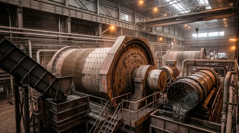
Working Principle
A ball mill reduces material size through two physical mechanisms: impact and attrition.
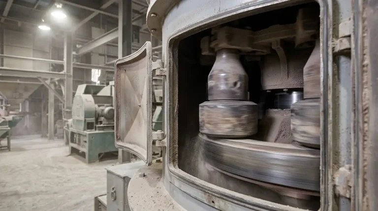
The cylindrical shell rotates on a horizontal axis. Inside, grinding media (steel or ceramic balls) and feed material tumble together. As the shell turns, balls are lifted by the liners to a certain height, then fall and strike the material below—this is impact. Simultaneously, balls roll and slide against each other and against the shell wall, creating friction that further breaks down particles—this is attrition.
Three motion regimes and their effect on grinding:
| Motion Regime | Speed Range | Grinding Effect |
|---|---|---|
| Cascading | Below ~50% of critical speed | Balls roll over each other; weak impact; low efficiency |
| Cataracting | 65%–80% of critical speed | Parabolic trajectory; strong impact and attrition combined — optimal |
| Centrifuging | At or above critical speed | Balls cling to shell; no grinding occurs |
Critical speed formula:
Nc (rpm) = 42.3 / √D
where D is the internal mill diameter in meters. Most industrial ball mills operate at 65%–79% of critical speed. According to Paul O. Abbe, dry mills typically run between 60% and 65% of critical speed.
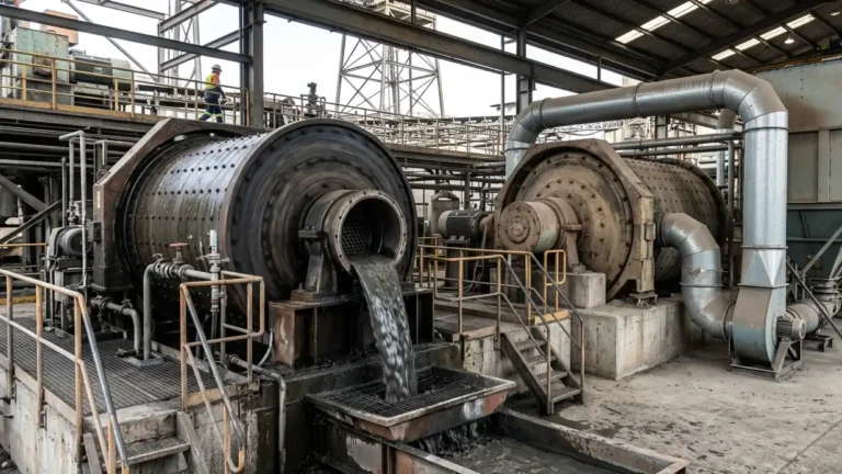
Wet vs. dry grinding:
- Wet grinding: Water is added to form a slurry. Energy consumption is roughly 20%–30% lower than dry grinding, dust generation is minimal, and it suits most continuous ore-processing circuits.
- Dry grinding: No water is required. Used for moisture-sensitive materials such as cement clinker and certain chemicals. Dust collection systems are mandatory.
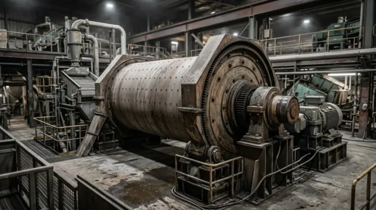
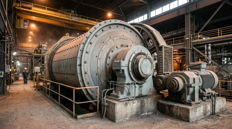
Key Components and Structure
Understanding what each part does is the prerequisite for correct operation and maintenance. Below is a breakdown of the ball mill’s core structure.
Main components:
| Component | Function |
|---|---|
| Mill Shell | Main cylindrical body; fabricated from high-strength wear-resistant steel plate |
| Mill Liners | Protect the shell from abrasion; lift grinding media; replaced periodically |
| Grinding Media | Steel or ceramic balls (typically 20–100 mm diameter); selected based on material hardness |
| Girth Gear & Pinion | Transfer motor torque to the rotating shell |
| Trunnion Bearings | Support both ends of the shell; require continuous lubrication |
| Feed System | Delivers material into the mill through the feed hollow shaft |
| Discharge System | Overflow or grate type; controls product particle size |
| Drive System | Motor, gearbox, and couplings; provides stable rotational speed |
| Lubrication System | Supplies oil to bearings and gears; prevents overheating and wear |
Grinding media selection guide:
- Steel balls: Best for hard materials (ores, limestone); provide strong impact force
- Ceramic balls: Preferred for applications where iron contamination is unacceptable (pharmaceuticals, food, fine chemicals)
- Smaller ball diameter → finer product; larger ball diameter → suitable for coarse grinding stages
Installation and Commissioning
Correct installation determines long-term reliability. According to the MR CRUSHER installation guide, after mechanical assembly is complete, a no-load test run of at least 12–24 hours is required before phased load testing begins.
Installation sequence:
- Foundation inspection: Verify foundation strength, levelness, and anchor bolt placement against design drawings
- Shell positioning: Use lifting equipment to lower the shell onto bearing pedestals; check trunnion-to-bearing concentricity
- Liner installation: Install shell liners per the manufacturer’s drawing; torque all liner bolts to specification
- Drive alignment: Motor shaft, gearbox shaft, and pinion shaft alignment error must be within 0.1 mm
- Lubrication system connection: Install oil station, pipework, and bearing seals; fill with the specified lubricant grade
- No-load test run: Run continuously for 12–24 hours; monitor temperature rise, noise, vibration, and motor current
- Phased load test: Load 1/3 of the designed grinding media charge first; run for 12–24 hours; then increase to full load
Commissioning acceptance criteria (reference values):
| Parameter | Normal Range |
|---|---|
| Trunnion bearing temperature rise | ≤35°C (max. 65°C absolute) |
| Gearbox oil temperature | ≤70°C |
| Shell vibration (horizontal) | ≤0.1 mm |
| Motor current | Not exceeding 110% of rated current |
Pre-Start Checklist
Running a pre-start check before every shift is the most cost-effective way to prevent unplanned stops.
Pre-start checklist (printable):
- Shell and end cover bolts are tight; no visible liner damage or missing sections
- Grinding media charge level is within design range (typically 30%–45% of mill volume)
- Feed chute is clear; no blockages or foreign objects
- Trunnion bearing oil level is normal; oil is clean, no emulsification
- Lubrication oil station pressure gauge reads normal (start the lube station before the main drive)
- Girth gear and pinion show intact oil film; no dry contact marks
- Motor wiring connections are tight; insulation resistance is acceptable (>1 MΩ)
- All guards and safety covers are in place and secured
- Emergency stop buttons are functional and unobstructed
- No unauthorized personnel in the work zone; access paths are clear
Important: The lubrication oil station must be started at least 3–5 minutes before the main mill drive to allow the bearing oil film to fully establish.
Step-by-Step Operating Procedure
Step 1 — Feed preparation
- Confirm feed material particle size is within the mill’s design specification (typically ≤25 mm)
- Set feed rate per the process design; avoid overfeeding, which causes the mill to “belly up”
- For wet grinding, open the water supply line; verify water flow matches target slurry density
Step 2 — Start-up sequence
The start-up order is critical to protecting equipment:
- Start the lubrication oil station (3–5 minutes before main drive)
- Start the cooling water system
- Engage the slow-speed barring device; confirm the shell rotates freely without obstruction
- Start the main motor (using soft-start or reduced-voltage starting); after stable speed is reached, engage the clutch
- Begin feeding at a low rate; gradually ramp up to the normal operating rate
Step 3 — Monitoring during operation
| Parameter | Normal Condition | Warning Sign |
|---|---|---|
| Motor current | Stable near rated value | Consistently high → overload; consistently low → under-grinding |
| Trunnion bearing temperature | ≤65°C | Above 70°C → check lubrication immediately |
| Discharge particle size | Meets process specification | Too coarse → check media charge and speed |
| Operating noise | Steady grinding sound | Metal-on-metal banging → check liners or media |
| Shell vibration | Slight, steady | Sudden increase → check anchor bolts and feed rate |
Step 4 — Sampling and particle size verification
Take a discharge sample every 1–2 hours and perform sieve analysis to verify product fineness. If output is too coarse, first check grinding media charge and feed rate. If output is too fine and throughput has dropped, consider increasing the feed rate slightly.
Step 5 — Discharge and shutdown
- Stop the feed; allow remaining material to grind out and discharge (typically 5–10 minutes)
- Stop the main motor; wait for the shell to come to a complete stop
- Shut down the cooling water and feed systems
- Wait at least 20 minutes after main motor shutdown before stopping the lubrication oil station
- Record all operating parameters for the shift
Safety Considerations
Ball mills are heavy rotating equipment, and safety protocol must be non-negotiable. Studies in industrial safety have found that approximately 60% of grinding-related accidents stem from procedural non-compliance or missing guards.
Required personal protective equipment (PPE):
- Hard hat: Protection from overhead falling objects
- Ear protection (≥25 dB NRR): Ball mills typically operate above 85 dB; prolonged exposure without protection causes permanent hearing damage
- Dust mask (≥N95): Mandatory for dry grinding operations; silica dust is a recognized occupational hazard
- Safety glasses: Protection from material splatter, especially during wet grinding
- Non-slip safety footwear: Essential in areas where slurry may accumulate on walking surfaces
Operational safety rules:
- Never open inspection hatches or touch rotating components while the mill is running
- Before any maintenance work, follow the complete LOTO (Lock-Out/Tag-Out) procedure: isolate the main power, lock the isolator, and attach a personal tag
- Never insert tools or limbs into the feed end while the shell is rotating
- If abnormal noise, vibration, smoke, or burning smell is detected, press the emergency stop immediately—do not wait to identify the cause first
- For confined space entry (shell interior inspection), a standby attendant outside the mill is mandatory at all times
Emergency shutdown sequence: Press emergency stop → Notify control room → Cut feed supply → Wait for shell to stop → Confirm power lockout → Investigate cause
Control and Automation
Modern industrial ball mills increasingly operate within automated control systems. These systems do not replace operator judgment—they provide continuous data to inform better decisions.
Key parameters for monitoring and control:
| Parameter | Control Objective | Typical Sensor |
|---|---|---|
| Mill load | Maintain optimal media-to-material ratio | Vibration sensor, acoustic sensor |
| Motor power draw | Reflect grinding performance; avoid overload or under-load | Power transducer |
| Discharge particle size | Adjust feed rate and media replenishment in real time | Online particle size analyzer |
| Trunnion bearing temperature | Trigger alarm before bearing damage occurs | RTD / thermocouple |
| Lubrication oil pressure | Confirm oil film formation | Pressure transmitter |
Typical PLC/DCS functions:
- Interlocked start/stop sequences to prevent operating errors
- Multi-level alarms for high temperature, overload, and low oil pressure
- Historical data logging for equipment condition trend analysis
- Remote monitoring to reduce the need for physical inspection rounds
In advanced operations, machine learning modules are being integrated to automatically adjust operating parameters in response to changes in ore hardness, further reducing specific energy consumption per tonne processed.
Troubleshooting Guide
| Fault Symptom | Probable Causes | Corrective Action |
|---|---|---|
| Trunnion bearing overheating (>70°C) | Insufficient or degraded lubricant; bearing clearance too tight; cooling water supply interrupted | Check oil level and quality; adjust bearing clearance; restore cooling water |
| Abnormal noise (metallic banging) | Loose or broken liner; excessive media charge; insufficient feed | Shut down and check liner bolts; adjust media charge; increase feed rate |
| Product particle size too coarse | Grinding media severely worn; speed too low; feed rate too high | Replenish or replace media; adjust speed; reduce feed rate |
| Throughput decline | Worn liners reducing media lift; low media charge; classifier malfunction | Inspect liner condition; add grinding balls; check classification equipment |
| Motor current persistently high | Overfeeding (“belly-up”); excessive media charge; drive system obstruction | Reduce feed rate; reduce media; inspect drive components |
| Increased shell vibration | Loose foundation anchor bolts; foundation settlement; uneven feed | Retighten anchor bolts; inspect foundation; stabilize feed rate |
| Slurry leakage | End cover seal worn; feed pipe angle misaligned; seal ring degraded | Replace sealing components; realign feed pipe (see Brazil graphite ball mill case study) |
Summary
Effective ball mill operation is the result of managing every stage systematically rather than reacting to problems as they arise. Understanding the impact-and-attrition grinding mechanism gives operators the foundation to interpret what the machine is telling them during normal operation. Knowing each component’s role makes pre-start inspections meaningful rather than routine. Following the correct installation and commissioning sequence prevents premature failures that often trace back to alignment or lubrication errors made on day one. A structured pre-start checklist and a clear step-by-step operating procedure reduce variability and protect both equipment and personnel. Modern control and automation systems amplify all of this by providing continuous visibility into mill performance. When faults do occur, systematic diagnosis consistently outperforms trial-and-error replacement of parts. For detailed specifications on MR CRUSHER ball mills, visit the MQ Ball Mill product page.
FAQ
Does longer grinding time always produce finer output?
Not necessarily. Over-grinding generates excessive ultrafines, wastes energy, and can reduce downstream recovery rates (notably in flotation circuits). The optimal grinding time should be determined by regular sampling and sieve analysis, not by simply running longer.
How often should grinding balls be replenished?
There is no universal fixed schedule. Monitor discharge particle size and motor current trends as the primary indicators. A common practice is to replenish balls at a defined rate per tonne of material processed (e.g., every 500–1,000 tonnes) and conduct a full media charge audit monthly.
Can a ball mill run continuously without stopping?
Industrial ball mills are designed for continuous operation. However, liner wear and grinding media depletion require periodic planned shutdowns for inspection and replacement. A preventive maintenance stop every 2,000–4,000 operating hours is a typical interval; actual frequency depends on ore abrasiveness and equipment condition monitoring data.
How do I choose between wet and dry grinding?
The choice depends primarily on material properties and downstream process requirements. Ore beneficiation operations generally use wet grinding because the slurry feeds directly into flotation or leaching circuits. Cement, certain chemical applications, and moisture-sensitive materials call for dry grinding. Wet grinding offers 20%–30% lower energy consumption but requires slurry handling infrastructure; dry grinding requires effective dust collection.
What parameters control discharge particle size?
Discharge fineness is determined by the combination of grinding media size and charge level, mill rotational speed, feed rate, and (in continuous mills) material residence time inside the shell. To achieve a finer product, reduce media diameter, lower the feed rate, or install more efficient classification equipment in a closed circuit with the mill.