

Hydraulic Impact Crusher (PFW) Explained: Structure, Configurations, and Full Model Range
What You Will Learn from This Guide
The PFW Hydraulic Impact Crusher is a redesigned, hydraulically adjusted evolution of the PF impact crusher. This guide covers what the hydraulic frame actually does. It also covers why PFW splits into two distinct duty-stage variants, rather than one continuous range, and how to choose between them. It serves a buyer or engineer evaluating the PFW specifically, and after reading, you will understand the reasoning behind its two-variant structure, not just its spec sheet numbers.
This guide assumes some familiarity with impact crusher basics. For the working principle and wear part material strategy shared across this product family, see this project’s PF Impact Crusher guide first.
The Hydraulic Frame: Why It Opens
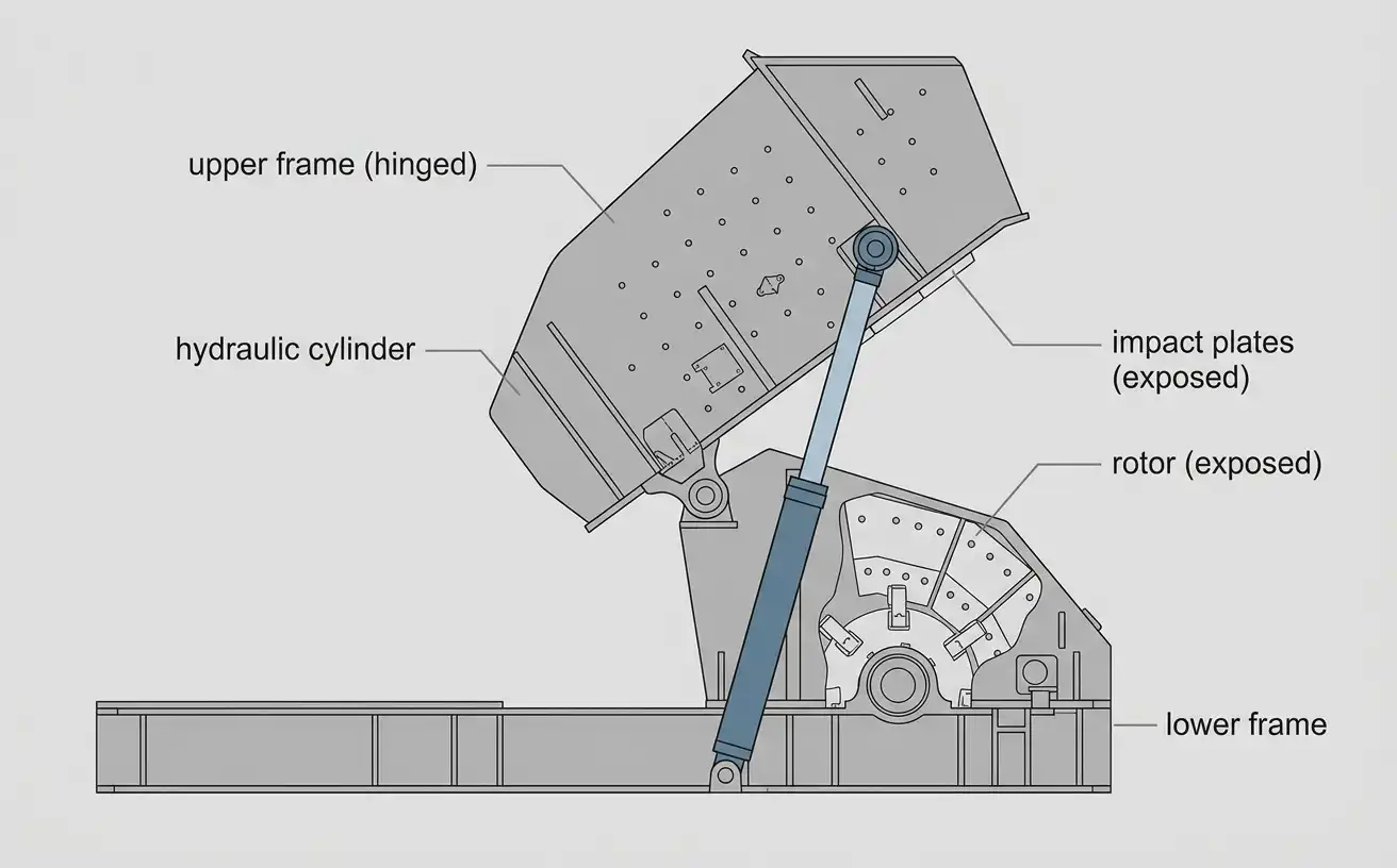
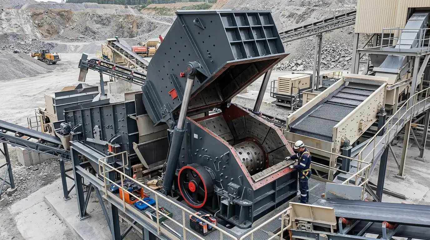
The PF uses a bolted frame. Reaching the rotor or impact plates for inspection means unbolting panels by hand. The PFW replaces that with a hinged upper frame, lifted open by a hydraulic cylinder.
This single change affects far more than convenience. A bolted frame turns a routine wear-part check into a planned, multi-step task. A hydraulic frame turns the same check into something closer to a few minutes of cylinder travel. Sites with frequent inspection needs feel this difference directly in uptime.
The hydraulic system typically pairs with a hydraulic gap adjustment as well. Setting the gap between rotor and impact plates no longer requires a manual shim or bolt change. It becomes a controlled adjustment made through the same hydraulic system that opens the frame.
Two Duty-Stage Variants: II for Coarse, III for Medium
The PFW line splits into two model families, marked by a II or III suffix. This is not a size variation within one product. It is two distinct duty-stage configurations built for different jobs.
The II variant handles coarse crushing. It has a larger feed opening, ranging from about 1,100 to 1,450 millimeters across the size range. It suits primary or coarse-stage duty, and its internal layout is closer to a standard two-plate impact arrangement.
The III variant handles medium, secondary-stage crushing. Its feed opening is smaller, from about 570 to 800 millimeters. It is designed to take feed already reduced by an earlier stage, not raw blasted rock. The defining feature of the III variant is a third impact plate, adding another crushing stage inside the same machine.
The Third Chamber: What Makes III Different
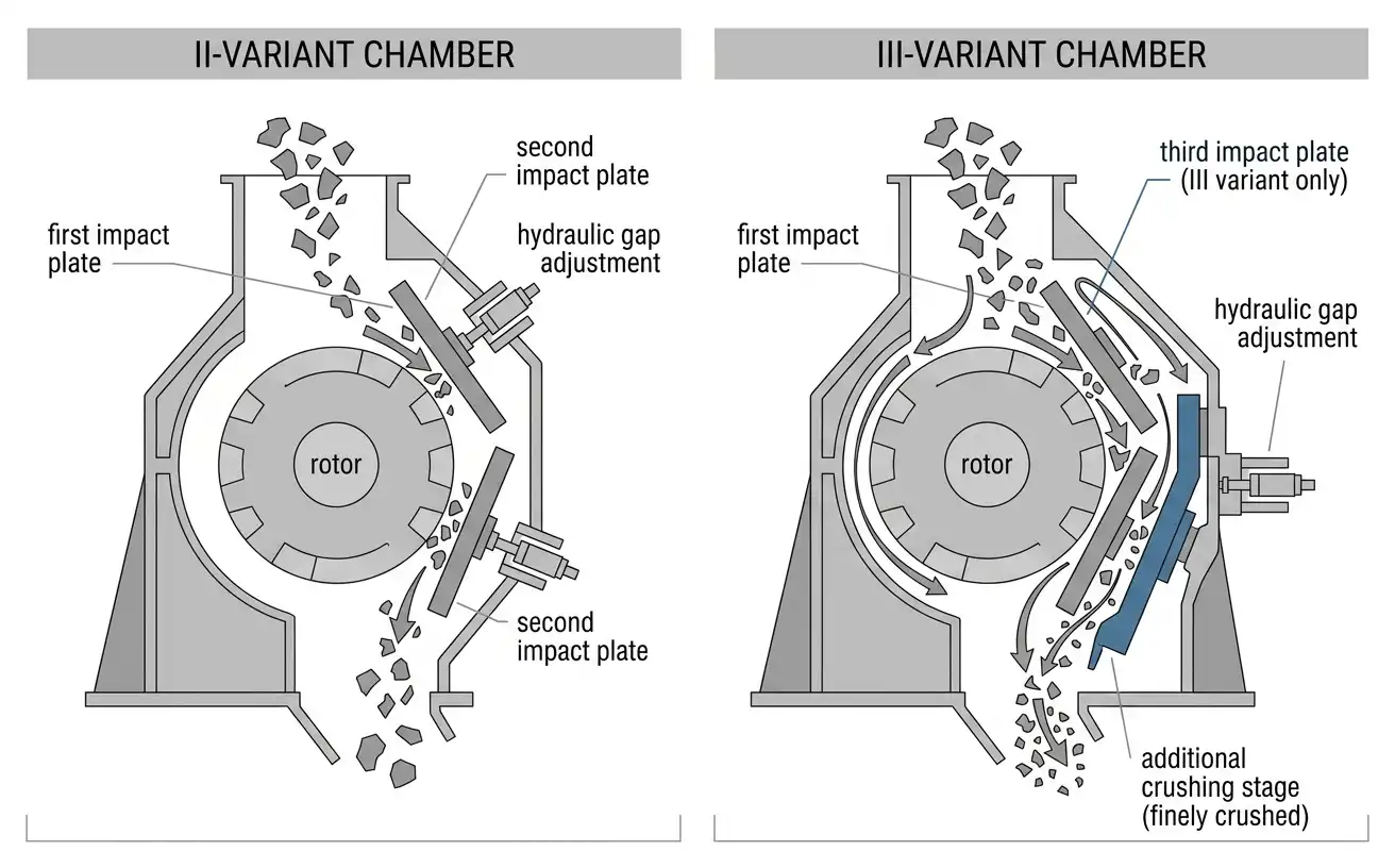
A standard impact crusher chamber uses two impact surfaces in sequence. Material strikes the rotor, then an impact plate, cycling between the two until it passes through the gap. The III variant adds a third impact plate in that sequence. This gives material one more controlled collision before it exits.
Multi-plate hydraulic designs typically let one adjustment govern the critical final gap. The earlier plates’ gaps follow from that same mechanism. The last plate in the sequence controls final particle size most directly, since it is the last surface material touches before leaving the chamber.
This extra stage is what lets the III variant produce a finer, more tightly graded product. A two-plate design working the same feed cannot match that result. It is also why the III variant suits producing high-quality sand and fine aggregate specifically, rather than the coarser output a II-variant machine targets.
Full PFW Model Range: Specifications
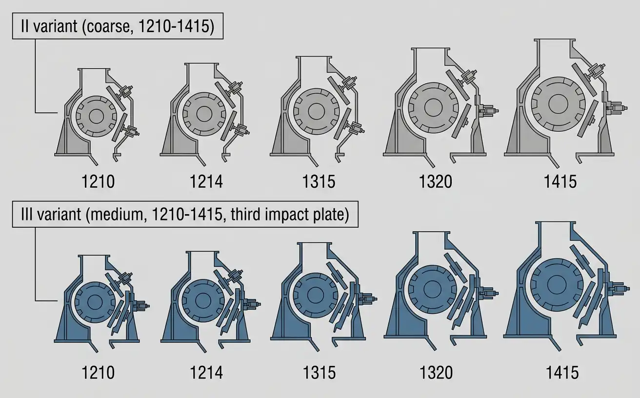
Table 1. PFW II variant (coarse crushing) specifications
| Model | Rotor (mm) | Feed Opening (mm) | Max Feed (mm) | Capacity (t/h) | Power (kW) |
|---|---|---|---|---|---|
| PFW1210II | Φ1150×960 | 1100×1030 | 400 | 90–160 | 90–110 |
| PFW1214II | Φ1150×1400 | 1100×1430 | 500 | 130–200 | 132–160 |
| PFW1315II | Φ1300×1500 | 1200×1530 | 600 | 180–320 | 160–200 |
| PFW1318II | Φ1300×1800 | 1200×1830 | 700 | 240–400 | 200–250 |
| PFW1415II | Φ1400×1500 | 1450×1530 | 800 | 260–450 | 200 |
Table 2. PFW III variant (medium crushing) specifications
| Model | Rotor (mm) | Feed Opening (mm) | Max Feed (mm) | Capacity (t/h) | Power (kW) |
|---|---|---|---|---|---|
| PFW1210III | Φ1150×960 | 570×990 | 250 | 70–140 | 90–110 |
| PFW1214III | Φ1150×1400 | 570×1430 | 250 | 90–170 | 132–160 |
| PFW1315III | Φ1300×1500 | 625×1530 | 300 | 180–270 | 160–200 |
| PFW1318III | Φ1300×1800 | 625×1830 | 300 | 220–300 | 200–250 |
| PFW1415III | Φ1400×1500 | 800×1530 | 350 | 280–350 | 200 |
Source: mrcrushermill.com PFW Hydraulic Impact Crusher product documentation.
Both variants share the same five rotor sizes, from 1210 through 1415. That shared numbering makes it easy to match a II model to its III counterpart on the same base machine size. Feed opening and max feed size still differ sharply between the two variants at each size, even when the rotor size number matches.
Selecting the Right PFW Configuration
Start with duty stage, not size. Raw, freshly blasted material calls for a II variant. Material already reduced by an earlier crushing stage, headed toward a fine, graded final product, calls for a III variant instead. Choosing the wrong variant for the feed condition causes problems no amount of size selection can fix.
Once duty stage is settled, size follows the same logic used across this product family. Match target capacity to the range first. Then confirm feed size against the model’s rated maximum.
The II and III variants at the same base size share rotor dimensions. Their feed openings and capacities do not overlap, though. Switching variants at the same nominal size is not simply a drop-in change.
Applications by Material and Industry
The II variant fits primary and coarse-stage duty on medium-hard and soft rock, much like the standard PF line it descends from. The III variant fits secondary, sand-making duty specifically. It takes pre-crushed feed and produces a fine, tightly graded product. That product suits concrete aggregate and manufactured sand specifications.
Sites running a full crushing circuit often pair the two variants in sequence. A II-variant machine handles the coarse stage. It feeds a III-variant machine for the finishing stage.
This two-stage arrangement inside one product line offers a genuine alternative. It can replace pairing an impact crusher with a separate cone or VSI crusher for the fine stage.
Maintenance: The Hydraulic Advantage
The hydraulic frame’s main maintenance benefit is access speed, not a change in what wears out. Blow hammers and impact plates on a PFW wear the same way they would on a bolted-frame machine. The material strategy behind them follows the same reasoning covered in the PF guide.
What changes is how quickly a worn part gets replaced once identified. Faster access through the hydraulic frame means shorter downtime per wear-part change. This matters even more on the III variant specifically, since its third impact plate now needs periodic access alongside the first two.
Frequently Asked Questions
What is the difference between PFW’s II and III variants?
The II variant is built for coarse crushing, with a larger feed opening suited to raw or lightly reduced material. The III variant is built for medium, secondary crushing, with a smaller feed opening and a third impact plate. They are different duty-stage configurations, not just different sizes.
What does the third impact plate on the III variant actually do?
It adds one more controlled collision to the crushing sequence, after the rotor and the first two impact surfaces. The last plate in that sequence controls final particle size most directly. That is why the III variant produces a finer, more tightly graded output than a standard two-plate design.
Why does the hydraulic frame matter beyond convenience?
A bolted frame turns a routine inspection into a planned, multi-step task. A hydraulic frame turns the same inspection into a few minutes of cylinder travel. Sites needing frequent access to wear parts see that time difference show up directly in uptime.
Can a II-variant machine be converted to III duty, or the reverse?
Not as a simple field change. The two variants differ in feed opening and internal chamber layout, including the III variant’s added third impact plate. Switching duty stage at the same base size means a different machine configuration, not just an adjustment.
References and Sources
- U.S. Patent 7,293,727 — Crusher and Mobile Crushing Machine Equipped with the Crusher
- Pit & Quarry — P&Q University Lesson 7: Crushing & Secondary Breaking
- U.S. Patent 11,000,854 — Rotor Positioning Device
- National Institute of Technology Rourkela — Design and Analysis of a Horizontal Shaft Impact Crusher