

The Science Behind Raymond Mill Swing Speed and Centrifugal Force
What determines swing speed and centrifugal force in a Raymond mill? The grinding roller in a Raymond mill swings outward against the grinding ring because of centrifugal force, and that force follows the physics relationship F = mω²r, where m is roller mass, ω is angular velocity, and r is the roller’s orbital radius. Because force scales with the square of rotational speed, a 20% increase in roller speed raises centrifugal force by roughly 44%, not 20%. Manufacturers fix each Raymond mill model’s rotational speed within a narrow rated band so that centrifugal force produces enough grinding pressure to crush the feed material without exceeding the mechanical limits of the bearings, grinding ring, and drivetrain. Running a mill above its rated speed increases grinding pressure, but it also raises vibration, wear, and the risk of flake formation on the grinding ring, so speed is not a variable an operator can raise freely to increase output.
What You Will Learn from This Guide
This guide explains the mechanical relationship between roller rotation, centrifugal force, and grinding pressure inside a Raymond mill, and shows how that relationship shapes model selection, fineness control, and maintenance planning. It serves an engineer or buyer who has already identified a Raymond mill as a candidate grinding technology and now needs to compare models, verify a duty-point specification, or diagnose a vibration or output problem tied to rotational speed. You will see how the five MGW model sizes distribute roller and ring dimensions differently, how grinding pressure is derived from rotational speed rather than set directly by an operator, and how two documented installations processing barite and calcium oxide responded to speed-related vibration and wear in the field. After reading this guide, you will be able to specify a Raymond mill duty point that accounts for material hardness and feed size, instead of requesting “the fastest available model,” and you will recognize the early signs that a mill is running outside its intended speed-pressure window.
Overview: What Swing Speed and Centrifugal Force Mean in a Raymond Mill
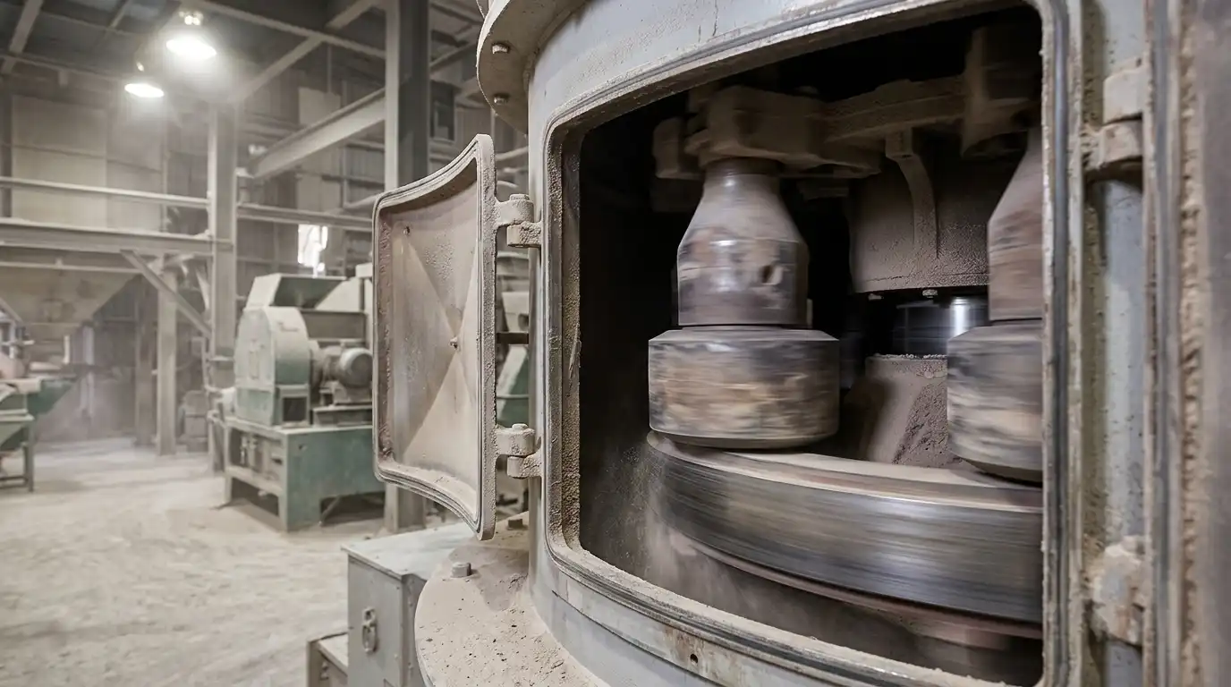
On the MGW Intelligent Raymond Mill and similar pendulum-roller designs, the grinding rollers hang from a rotating frame, sometimes called a spider or roller hanger. As the frame turns, each roller both orbits the mill’s central axis and spins on its own shaft. The orbital motion is what generates centrifugal force. Because the rollers are hinged rather than rigidly fixed, centrifugal force swings each roller outward until it presses against the stationary grinding ring. Swing speed refers to the rate of this orbital rotation, measured in revolutions per minute (rpm) of the main shaft. Centrifugal force refers to the outward force this rotation produces on each roller.
These two quantities are not independent settings. Centrifugal force is a direct mathematical function of swing speed, roller mass, and orbital radius, not a value an operator sets on a control panel. On a Raymond mill, grinding pressure emerges from how fast the main shaft turns and how heavy the roller assembly is, unlike a hydraulic press, where pressure is set with a valve. This centrifugal mechanism is why rotational speed is fixed within a narrow band for each model rather than adjusted freely during operation, a constraint documented in the 12 t/h Raymond mill installation grinding barite covered next.
Working Principle: How Centrifugal Force Creates the Pendulum Swing
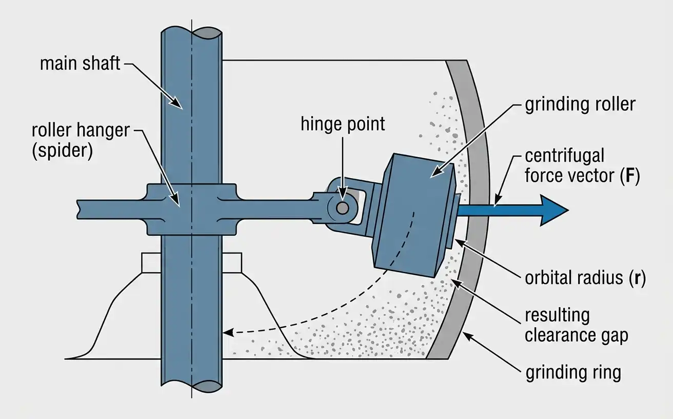
Newtonian mechanics explains why the grinding roller inside the MGW Intelligent Raymond Mill swings outward instead of hanging straight down from its hinge. The relevant formula is F = mω²r, where F is the outward force in newtons, m is the mass of the roller assembly in kilograms, ω is the angular velocity in radians per second, and r is the radius from the mill’s central axis to the roller’s center of mass. Angular velocity relates to rotational speed through ω = 2πn/60, where n is rotational speed in rpm. Combining these two relationships shows that centrifugal force is proportional to the square of rotational speed: doubling the rpm quadruples the force, with mass and radius held constant.
U.S. Patent No. 4,682,738, filed for a centrifugal ring-roller mill in the design lineage of the Raymond ring-roller mill, states this relationship directly. It notes that centrifugal force “varies in accordance with the rotational speed and weight of the rollers,” and that increasing rotational speed to raise output produces “an excessively high grinding pressure” that compresses fine particles into flakes, increases vibration and noise, and accelerates wear on the rollers and grinding ring.[1] This is why Raymond mill manufacturers do not treat rotational speed as a free variable. Each model uses a fixed reduction ratio between the motor and the main shaft, which locks roller orbital speed to a narrow rated range rather than leaving it adjustable by the operator.
Table 1 expresses this relationship in relative terms. Because roller mass and orbital radius cancel out when comparing two forces on the same roller, the table needs no assumption about roller weight or exact radius. It applies to any Raymond mill roller operating above or below its rated speed.
Table 1. Relative Centrifugal Force as a Function of Rotational Speed Deviation from Rated Speed
| Rotational Speed (% of Rated) | Relative Angular Velocity (ω/ω₀) | Relative Centrifugal Force (F/F₀) | Documented Effect at This Level |
|---|---|---|---|
| 80% | 0.80 | 0.64 | Grinding bed forms unevenly; incomplete crushing |
| 100% (rated) | 1.00 | 1.00 | Reference condition specified by the manufacturer |
| 110% | 1.10 | 1.21 | Grinding pressure rises approximately 21% |
| 120% | 1.20 | 1.44 | Grinding pressure rises approximately 44%; flake formation risk increases |
| 150% | 1.50 | 2.25 | Grinding pressure more than doubles; vibration and wear accelerate |
Source: values calculated from F = mω²r (Newtonian mechanics, ratio form); qualitative effects at each level are documented in U.S. Patent No. 4,682,738.
The table shows why a 10% speed increase does not produce a proportional 10% increase in grinding force. Because the relationship is squared, small deviations from rated speed compound quickly. A separate line of peer-reviewed research on vertical roller mills reached a related conclusion using a different grinding geometry: raising rotation speed while holding loading pressure and moisture constant increased energy consumption and lowered grinding energy efficiency, because higher speed raises motor power draw faster than it raises the yield of correctly sized particles.[2] The mechanism differs from a pendulum-type Raymond mill, but the direction of the effect is consistent across roller-based grinding equipment: raising speed alone does not translate into a proportional gain in usable output.
A 12 t/h Raymond mill installation grinding barite illustrates the practical side of this relationship. The mill’s rated speed was matched at the design stage to barite’s Mohs hardness of 3 to 3.5, and the field issue that emerged after commissioning was not roller speed but the abrasiveness of barite dust against the discharge piping at 2,500 meters above sea level, which was resolved with a wear-resistant ceramic lining rather than a speed change.
Types and Model Comparison: How Swing Speed Requirements Differ Across Raymond Mill Models
Each Raymond mill model size, from the smallest MGW Intelligent Raymond Mill configuration to the largest, sets roller dimensions, ring diameter, and motor power differently to reach a different capacity target. Because centrifugal force depends on both roller mass and orbital radius, a larger model is not simply a scaled-up version running at the same speed; roller geometry, ring diameter, and the rated rotational speed are engineered together to produce the grinding pressure that model needs.
Table 2. MGW Intelligent Raymond Mill Technical Specifications by Model
| Parameter | MGW110 | MGW138 | MGW175 | MGW198 | MGW215 |
|---|---|---|---|---|---|
| Rollers (pcs) | 4 | 4 | 5 | 5 | 5 |
| Roller diameter × height (mm) | 640 × 320 | 460 × 240 | 520 × 280 | 620 × 300 | 640 × 320 |
| Ring inner diameter × height (mm) | 1,100 × 190 | 1,380 × 240 | 1,750 × 280 | 1,980 × 300 | 2,150 × 320 |
| Maximum feed size (mm) | <30 | <35 | <40 | <50 | <50 |
| Final product size (mm) | 1.6–0.038 | 1.6–0.038 | 1.6–0.038 | 1.6–0.038 | 1.6–0.038 |
| Capacity (t/h) | 3.5–10 | 6.5–15 | 13–20 | 15–30 | 30–45 |
| Main mill motor power (kW) | 55 | 110 | 185 | 280 | 180 |
| Classifier motor power (kW) | 11 | 18.5 | 37 | 55 | 90 |
| Fan motor power (kW) | 55 | 110 | 200 | 280 | 315 |
Source: MGW Intelligent Raymond Mill technical specifications, manufacturer data.
Main mill motor power is the column most buyers use to shortlist a model, because motor power sets the torque available to bring the roller assembly up to rated rotational speed under load. A model with a motor sized below what its roller mass and ring diameter require will not sustain the rotational speed needed to generate rated grinding pressure, and output falls short of the capacity range shown, particularly on feed materials at the harder end of the mill’s rated hardness range.
Two related grinding technologies address requirements a Raymond mill’s centrifugal-force mechanism does not cover. The MSF Ultrafine Grinding Mill uses a different force mechanism to reach product fineness beyond the practical ceiling of spring- and centrifugal-force-based grinding, discussed further in the next section. The MQ Ball Mill uses impact and attrition from a tumbling steel or ceramic media charge instead of centrifugal roller force, which suits wet grinding and feed materials that are not well suited to a fixed roller-ring clearance.
Specifications and Parameters: How Model Size Sets the Available Grinding Pressure
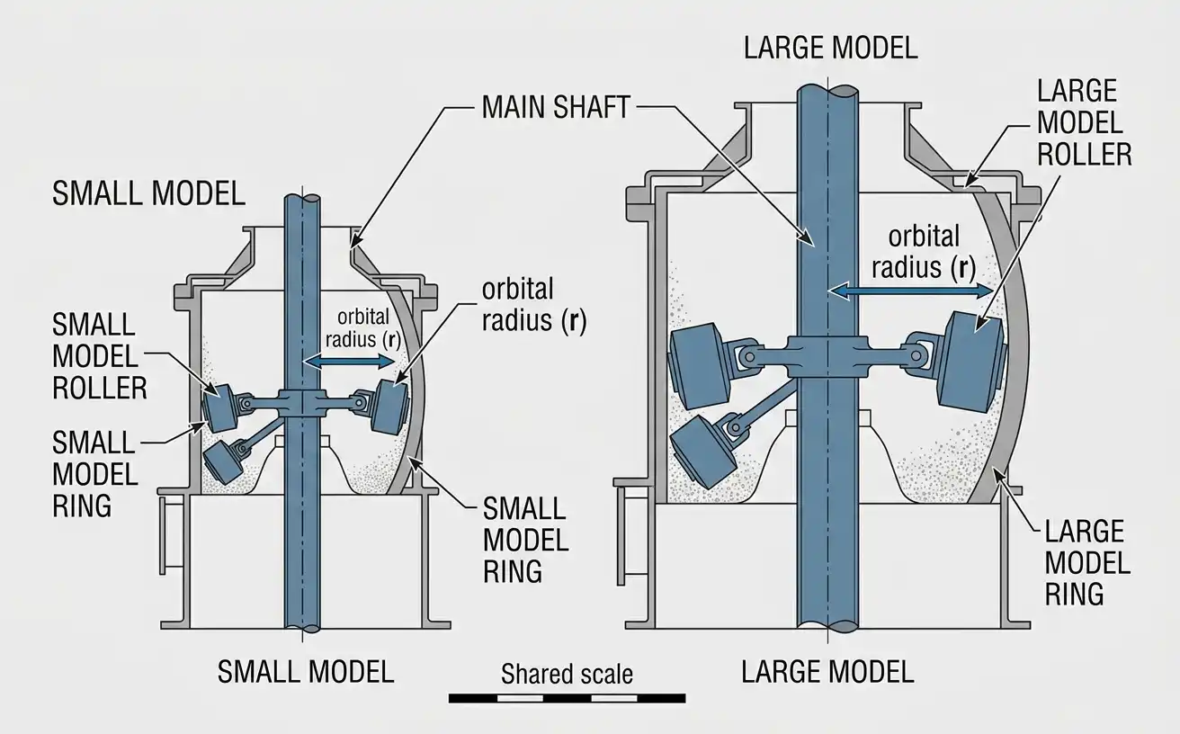
The 12–13 t/h Raymond MGW175 mill installation grinding calcium oxide, covered in detail below, shows how roller and ring dimensions translate into usable grinding pressure at a specific model size. Roller mass increases with roller volume, and orbital radius increases with ring diameter. Because centrifugal force depends on both variables through F = mω²r, a larger model can reach the grinding pressure it needs without requiring a proportionally higher rotational speed than a smaller model, since the added roller mass and radius contribute to force independently of speed. This is a mechanical design choice built into the roller and ring dimensions in Table 2, not an operating parameter a buyer selects separately.
Swing speed and classifier speed are two different rotating systems on the same machine, and this distinction matters when a buyer requests a specific product fineness. The main shaft and roller assembly set grinding pressure and are fixed by the drivetrain, as described above. Product fineness is controlled separately, by the classifier, whose motor power ranges from 11 kW on the MGW110 to 90 kW on the MGW215, as shown in Table 2. Raising classifier speed narrows the particle size that passes to the finished product outlet; it does not change roller swing speed or grinding pressure. A buyer who wants finer output should specify classifier requirements, not request a faster roller swing speed, since roller speed is fixed to protect the grinding ring and bearings.
The 12–13 t/h Raymond MGW175 mill installation grinding calcium oxide documents a case where uneven material buildup from highly fluid calcium oxide powder caused vibration in the mill body. The manufacturer’s response combined a reinforced cantilever roller structure, a high-damping shock-absorbing base, and dynamic balance correction, together with real-time current and vibration monitoring that automatically adjusts feed rate to keep the material layer inside the grinding chamber stable. The fix addressed material behavior inside the fixed speed-pressure window rather than changing the rated rotational speed itself.
Selection Criteria: Matching Centrifugal Force to Material Hardness and Feed Size
Selecting the correct model, illustrated by the 7 t/h Raymond mill MGW138 installation grinding bentonite covered below, starts with two variables: material hardness and feed particle size. The Mohs hardness scale, developed in 1812 and still used today as the standard reference for mineral scratch resistance, ranks materials from 1 (talc) to 10 (diamond).[4] The MGW Intelligent Raymond Mill line is rated for feed materials below Mohs hardness 9 and moisture content below 6%, but the effective ceiling for consistent output at rated capacity is lower, because harder feed increases the resistance the roller assembly must overcome at a fixed rotational speed, which increases wear rate rather than crushing more material per revolution.
Feed particle size is the second constraint tied to swing speed indirectly. Table 2 lists a maximum feed size for each model, from 30 mm on the MGW110 to 50 mm on the MGW198 and MGW215. Feed above this size does not fit into the clearance the roller establishes against the ring at rated speed, and oversized particles either block the feed path or pass through unground, reducing effective capacity even though the mill continues to operate at its rated rpm.
A 7 t/h Raymond mill MGW138 installation grinding bentonite illustrates how model selection accounts for both variables together: bentonite’s swelling behavior and moderate hardness were matched to the MGW138’s roller mass and rated speed at the proposal stage, rather than selected on capacity alone. Selecting a model by capacity number without checking hardness and feed size against Table 2 is a common specification error that shows up later as under-target output rather than as an equipment failure.
Applications by Material and Industry
Raymond mills serve industrial minerals processing across quarrying, chemical manufacturing, agriculture, and refining support industries, and the centrifugal grinding mechanism performs differently depending on the feed material’s hardness and moisture. A 15–26 t/h Raymond mill fertilizer grinding installation processes materials that are typically softer than industrial minerals but require tight fineness control for downstream blending, which places more demand on classifier tuning than on roller speed. A 4–5 t/h Raymond mill petroleum coke grinding installation processes a harder, more abrasive material used as a fuel and reducing agent, where roller and ring wear rate becomes the limiting factor on maintenance intervals rather than achievable fineness.
Materials such as barite, calcite, limestone, feldspar, mica, basalt, coal slag, potassium feldspar, and talc fall within the applicable range for the MGW Intelligent Raymond Mill line, provided feed size and hardness are checked against Table 2 and the Mohs hardness limit described above.[4] Materials above Mohs hardness 9, materials with moisture content above 6%, and explosive or flammable materials fall outside the intended application range for this centrifugal grinding mechanism, regardless of model size. Materials at the harder end of the applicable range shift the limiting factor from achievable fineness to wear part consumption, a pattern documented in the 1.5–2 t/h Raymond mill alumina grinding installation discussed in the next section.
Maintenance and Wear Parts: How Rotational Speed Affects Roller and Ring Life
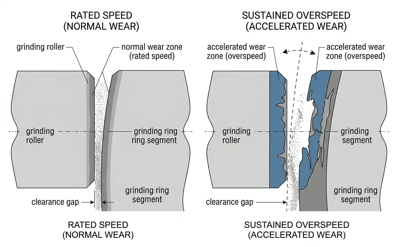
The 1.5–2 t/h Raymond mill alumina grinding installation introduced above makes wear planning, not achievable capacity, the central maintenance question. Roller and grinding ring wear rate rises faster than rotational speed itself, because wear is driven by the grinding pressure that speed produces, and that pressure rises with the square of speed, as shown in Table 1. A mill running 20% above rated speed does not wear its rollers and ring 20% faster; it operates at approximately 44% higher grinding pressure, and wear rate on abrasive materials tracks pressure more closely than it tracks speed alone.
Grinding rollers and grinding ring segments on Raymond mills are typically manufactured from abrasion-resistant white cast irons of the type specified in ASTM A532/A532M, which covers alloyed white cast irons engineered for high resistance to abrasive wear in mining, milling, and earth-handling applications.[3] Selecting a wear part material and hardness grade under this specification, matched to the feed material’s abrasiveness, extends service intervals more reliably than compensating for wear by increasing rotational speed, which raises pressure and accelerates the same wear it is meant to offset.
This installation grinds a feed material with higher hardness than most industrial minerals processed on the MGW line, and wear part replacement interval, not achievable capacity, is the primary maintenance planning variable for this application. Operators should inspect roller and ring clearance on a fixed schedule rather than waiting for an output drop, since clearance widens gradually as wear progresses and grinding pressure at a fixed rotational speed falls as clearance opens, which reduces output before it becomes visible as a mechanical fault. The same pressure-driven wear pattern applies to the harder, more abrasive feed handled in a 4–5 t/h Raymond mill petroleum coke grinding installation, where wear part interval is likewise the binding constraint on throughput.
Cost and Procurement: How Speed-Related Design Choices Affect Price and Lead Time
Motor power, roller and ring mass, and the drivetrain components that hold rotational speed within its rated band account for a significant share of a Raymond mill’s equipped cost, because these components are sized to the model’s rated capacity rather than to a generic average duty point. A 25–30 t/h Raymond mill calcium oxide production line at the upper end of the MGW capacity range requires a larger motor, heavier roller assembly, and larger grinding ring than a mill rated for a fraction of that throughput, and these components typically carry longer lead times than smaller-model equivalents because of their size and the reinforced bearing and drivetrain components needed to sustain rated speed under continuous load.
MR Crusher has not published aggregate lead-time or regional price-tier data across its installed base of Raymond mill projects. Buyers who need this level of procurement detail for a specific model, capacity, and destination can request a quotation referencing a comparable project, such as the 25–30 t/h Raymond mill calcium oxide production line described above, through the mill’s contact form, which routes the inquiry to the regional engineering team responsible for duty-point verification.
Frequently Asked Questions
What is the rotation speed of a Raymond mill?
Rotational speed varies by model size and manufacturer, and each Raymond mill model is designed to operate within a narrow rated rpm band rather than a single fixed number across all models. The rated speed for a given model is set by the reduction ratio between the motor and the main shaft and is not intended to be adjusted by the operator during normal use.
Why does the grinding roller in a Raymond mill swing outward?
The roller swings outward because of centrifugal force generated as the roller orbits the mill’s central axis. The roller is hinged to a rotating frame rather than fixed rigidly, so the outward force produced by rotation, described by F = mω²r, pushes the roller against the grinding ring until the ring’s resistance balances the force.
What happens if a Raymond mill runs faster than its rated speed?
Grinding pressure rises with the square of rotational speed, so a moderate speed increase produces a larger increase in pressure. Sustained overspeed operation raises vibration, accelerates wear on the roller and grinding ring, and increases the risk of fine particles compressing into flakes that adhere to the grinding ring instead of being carried to the classifier.
How is fineness controlled on a Raymond mill if roller speed is fixed?
Product fineness is controlled by the classifier, a separate rotating component with its own motor, rather than by the roller swing speed. Raising classifier speed narrows the particle size range that passes through to the finished product, independent of the grinding roller’s rotational speed. For fineness targets beyond the practical range of a classifier-equipped Raymond mill, the MSF Ultrafine Grinding Mill uses a different grinding mechanism designed for finer output.
Can centrifugal force in a Raymond mill be increased without raising rotational speed?
Yes. Because F = mω²r, force can also be increased by adding roller mass or increasing the orbital radius, which is why larger Raymond mill models use larger rollers and larger grinding rings rather than simply running smaller rollers at a higher rpm to reach the same grinding pressure.
References & Sources
- U.S. Patent No. 4,682,738 — Grinding Mill (United States Patent and Trademark Office)
- Liu, C. et al. — Analysis and Optimization of Grinding Performance of Vertical Roller Mill Based on Experimental Method, Minerals 2022, 12(2), 133 (MDPI)
- ASTM A532/A532M-10(2019) — Standard Specification for Abrasion-Resistant Cast Irons (ASTM International)
- U.S. Geological Survey — Mohs Hardness Scale