Ball Mill Dimensions & Size Selection Guide: D×L Charts, Capacities, and L/D Ratios Explained
Ball mills are the workhorses of mineral grinding circuits—and also the biggest energy consumers on most mine sites. Getting the dimensions right before you order matters enormously. A mill that’s too small leaves capacity on the table; one that’s too large burns kilowatts and capital on every shift. Whether you’re designing a new circuit from scratch or replacing aging equipment, this guide covers the standard sizing conventions (D×L), how the length-to-diameter ratio drives performance, how feed particle size shapes your selection, and the reference tables engineers use when specifying mills for mining, cement, and ceramics production.
Types of Ball Mills
The type you select shapes everything downstream—the L/D ratio, the discharge system, and the grinding media. Before getting into numbers, it’s worth understanding what’s available.
Wet vs Dry Grinding
Wet mills suspend the feed material in water. The resulting slurry flows through the mill and exits at the discharge end. Wet grinding produces finer particles more efficiently and eliminates dust—which is why it dominates in mining and mineral processing worldwide.
Dry mills operate without liquid. They’re used where water would damage the product (cement clinker, certain ceramics) or where water supply is limited. Dry mills typically need a higher L/D ratio and a robust dust collection system at the discharge end.
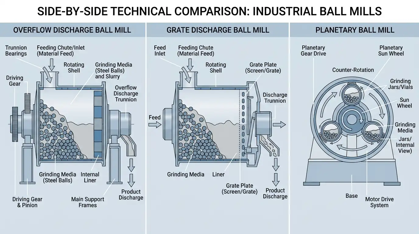
By Discharge Mechanism
| Discharge Type | Typical Fineness | Best For |
|---|---|---|
| Overflow | 75–106 µm and finer | Fine grinding, secondary circuits |
| Grate / Diaphragm | 150–250 µm | Coarse primary grinding, high throughput |
| Center-Periphery | 150–300 µm | Special dual-feed configurations |
Overflow mills are the most common globally. Material exits when the internal slurry level rises above the discharge trunnion. Simple, reliable, and ideal for fine grinding.
Grate discharge mills use a perforated plate that keeps coarser particles inside for additional grinding. They run with a lower internal slurry level, which reduces over-grinding and allows higher throughput for a given mill volume.
By Production Scale
- Laboratory (0.5–50 L): Batch testing, Bond work index determination, material characterization
- Pilot (50–500 L): Scale-up studies, process development
- Industrial (Φ1.5 m and larger): Continuous production in mining, cement, ceramics
For continuous industrial production, the MQ Ball Mill covers a wide capacity range from a few tons per hour up to hundreds of t/h, depending on mill dimensions and ore characteristics.
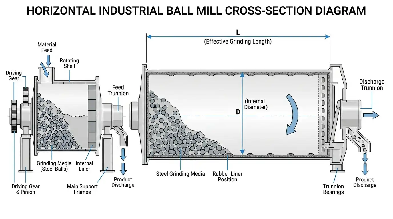
Ball Mill Dimensions: What D×L Actually Means
Ball mills are specified by two numbers: internal diameter (D) and effective grinding length (L). A mill labeled “2400×8000 mm” has an internal shell diameter of 2,400 mm and an effective grinding length of 8,000 mm.
Both measurements are taken inside the bare steel shell—before liners are installed. Once 65–75 mm rubber or steel liners go in, the working diameter shrinks accordingly. Always use the lined working diameter for critical speed and power draw calculations.
Why Diameter Drives Performance More Than Length
Diameter determines the two most critical operating parameters:
- Critical speed: Nc=42.3/DN_c = 42.3 / \sqrt{D} (rpm, where D is in meters). Recommended operating speed is 65–80% of Nc.
- Power draw: Power scales roughly with D²·⁴⁶. Doubling the diameter multiplies energy consumption by about 5.5×.
A larger diameter also increases the drop height of grinding media, generating more impact energy per revolution—useful for coarse, hard ore feed.
Liner Wear and Dimensional Drift
Liners wear down over time, gradually increasing the working diameter. A 70 mm liner worn to 30 mm adds 80 mm to the working diameter, which shifts the critical speed and power profile. Always start sizing calculations from the as-new lined dimensions, not the bare shell.
The Length-to-Diameter (L/D) Ratio
The L/D ratio is the most useful design shorthand for matching a ball mill to a specific application. It controls how long material stays inside the mill—and therefore how fine the final product gets.
| L/D Range | Mill Type | Typical Application | Product P₈₀ |
|---|---|---|---|
| 1.0–1.2 | Short mill | Primary grinding (coarse ore) | 300–600 µm |
| 1.3–1.8 | General purpose | Standard mining circuits | 100–300 µm |
| 2.0–2.5 | Long mill | Secondary / fine grinding | 45–150 µm |
| ≥ 3.0 | Tube mill | Cement, ultrafine applications | < 45 µm |
Primary vs Fine Grinding
For primary grinding—where feed comes straight from a crusher and F₈₀ exceeds 3,000 µm—a shorter L/D (1:1 to 1.3:1) is fine. The mill relies on impact energy from large balls hitting coarse particles.
For fine grinding in open circuit, 1.3:1 to 1.5:1 is standard. Closed-circuit mills with classifying cyclones can operate at lower L/D ratios because oversize material keeps circulating until it’s ground to specification.
When One Mill Isn’t Enough
Once your sizing calculation pushes the required diameter above 6 meters (roughly 20 feet), most manufacturers recommend running two mills in parallel instead. Two smaller mills are easier to maintain, allow independent process control, and eliminate the single-point-of-failure risk.
How Feed Particle Size Affects Mill Sizing
Feed particle size isn’t just an input to your capacity calculation—it directly determines the required ball size, which in turn sets the practical minimum mill diameter.
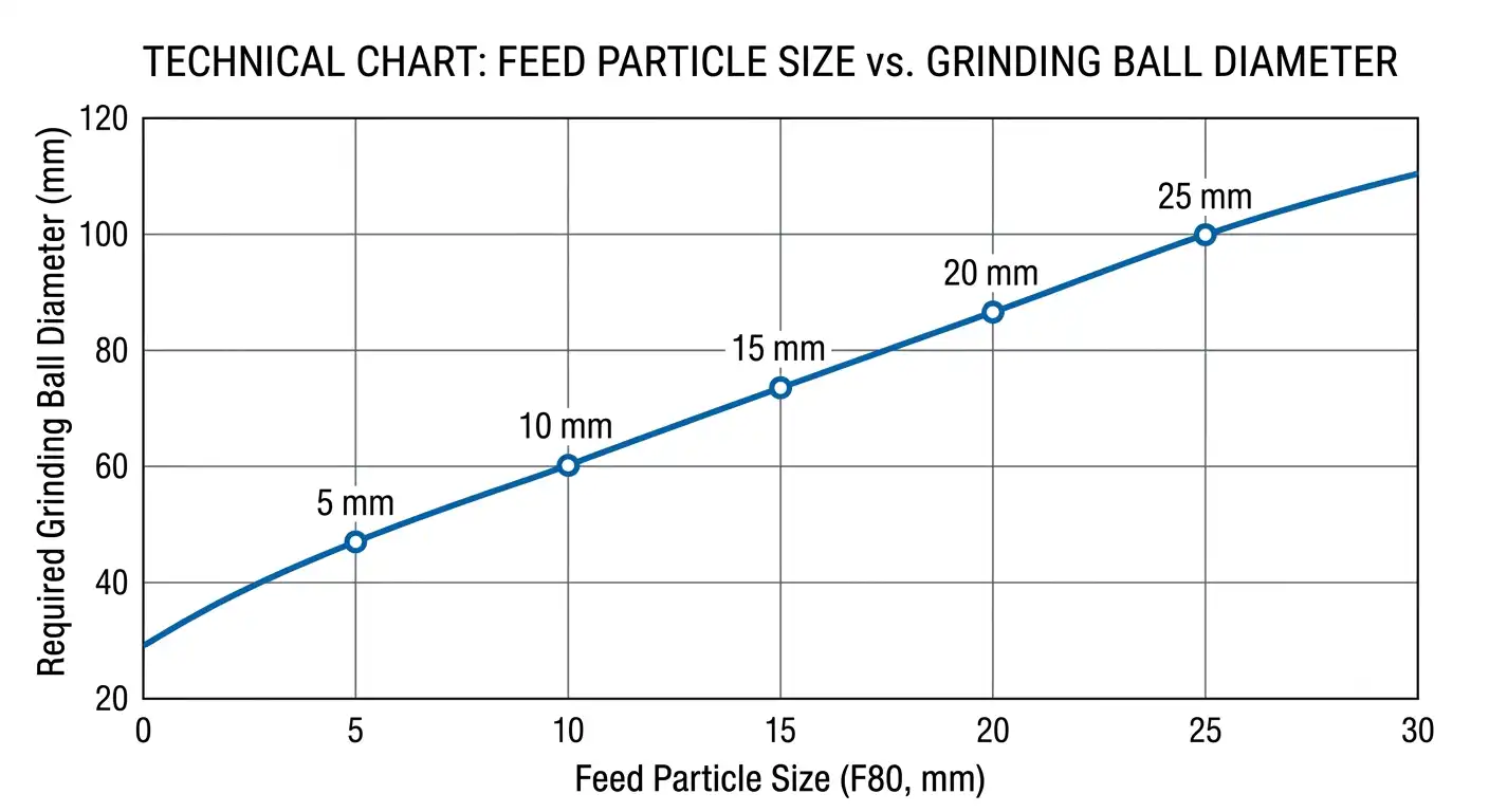
Ball Size Selection: Bond’s Formula
Fred Bond’s top ball size formula is widely used across the industry:
DB=25.4[F80k]0.5⋅[ρsWi100 ϕCD]0.33D_B = 25.4 \left[\frac{F_{80}}{k}\right]^{0.5} \cdot \left[\frac{\rho_s W_i}{100\, \phi_C \sqrt{D}}\right]^{0.33}
Where:
- F₈₀ = 80% passing size of feed (µm)
- k = mill factor (350 for wet overflow; 335 for wet grate)
- ρₛ = ore specific gravity
- Wᵢ = Bond Work Index (kWh/t)
- φ_C = fraction of critical speed
- D = mill inside diameter (m)
Coarser feed requires larger balls—typically 80–125 mm for primary grinding, down to 25–50 mm in fine regrind circuits.
The Role of Pre-Crushing
Ball mills are most efficient below a 25 mm feed size. Running coarser material through the mill wastes energy and accelerates liner and media wear. Pre-crushing with a PE jaw crusher or an HP multi-cylinder cone crusher reduces F₈₀ substantially, allowing smaller grinding balls and a smaller-diameter mill for the same throughput target. In most mining circuits, every dollar spent on pre-crushing saves two to three dollars in grinding energy.
Feed Size and Required Mill Length
Coarser feed needs more grinding time, which pushes toward a higher L/D or a longer closed-circuit residence time. Reducing F₈₀ from 6,000 µm to 2,000 µm—by adding a secondary cone crusher—can trim the required mill volume by 15–30%.
Feed and Discharge Systems
The hardware at each end of the mill has more influence on effective grinding volume than most engineers expect.
Feed Systems
| Feed System | Description | Best Application |
|---|---|---|
| Spout feeder | Gravity-fed tube, minimal moving parts | Cyclone closed-circuit (cyclone installed above mill) |
| Helical scoop feeder | Screw picks up classifier underflow | Rake classifier closed-circuit |
| Single / double drum feeder | Drum-shaped, tolerates tramp metal | Primary grinding circuits |
The top of the feed hopper should sit at least 1.5 m above the mill centerline to ensure consistent gravity-fed flow.
Discharge Systems
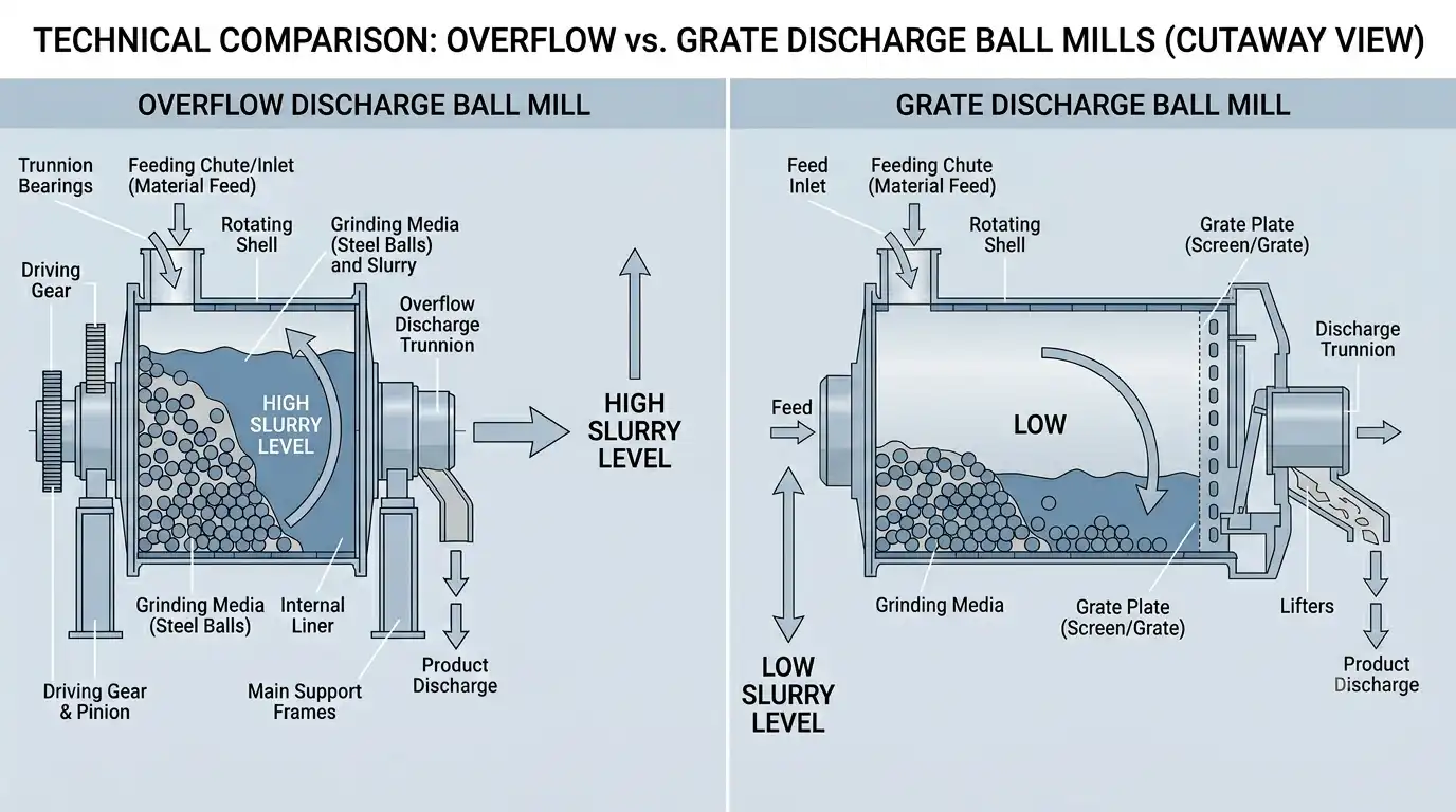
Overflow discharge: The discharge trunnion sits 5–110 mm below the mill centerline. Material exits naturally when slurry rises high enough. Low maintenance, good for fine grinding—but prone to over-grinding in oversized or open-circuit installations.
Grate discharge: A perforated plate at the discharge end retains coarse particles. Lower internal slurry level reduces over-grinding and increases throughput for a given mill size. Harder to maintain (grate plates wear and can plug), but the performance trade-off is clear for coarse-grinding applications.
The discharge type also affects how effective grinding length is measured—which explains why two mills with identical nameplate dimensions can have different working volumes depending on the manufacturer’s measurement convention.
Capacity and Throughput
Capacity is the result of five variables working together: mill volume, ball charge level, operating speed, ore hardness, and target product size. None of them operates in isolation.
Bond’s Capacity Equation
Bond linked mill capacity (Q, t/h) to shaft power (P_M, kW) and specific energy (E, kWh/t):
Q = P_M / E, where E=Wi(10P80−10F80)E = W_i \left(\dfrac{10}{\sqrt{P_{80}}} – \dfrac{10}{\sqrt{F_{80}}}\right)
A hard ore (Wᵢ = 18 kWh/t) ground from F₈₀ = 3,000 µm to P₈₀ = 150 µm requires roughly 17–19 kWh/t specific energy. A 500 kW mill running at that energy rate delivers approximately 26–29 t/h net throughput.
Real-World Capacity Examples
- 2–3 t/h ball mill for graphite ore: Φ900×1800 mm configuration, 18.5 kW motor
- 6 t/h ball mill for manganese ore: Φ1500×3000 mm mill, 75 kW motor
- 3–5 t/h ball mill for feldspar: Φ1200×2400 mm mill, 45 kW motor
These figures assume soft-to-medium hardness ore and product P₈₀ around 75–150 µm. Hard ore or a finer target size will reduce capacity by 20–50%.
Standard Ball Mill Size Reference Chart
The table below lists commonly manufactured industrial sizes. Capacity figures are indicative—actual throughput depends heavily on ore hardness (Bond Wᵢ), target product P₈₀, ball charge level, and circuit type. Use these numbers as a starting point for equipment comparison, not as a final specification.
| Model | Shell Dia. (mm) | Length (mm) | Volume (m³) | Motor (kW) | Approx. Capacity (t/h)* |
|---|---|---|---|---|---|
| Φ900×1800 | 900 | 1,800 | 0.8 | 18.5 | 0.65–2 |
| Φ1200×2400 | 1,200 | 2,400 | 2.7 | 45 | 1.5–5 |
| Φ1500×3000 | 1,500 | 3,000 | 5.3 | 75 | 2–7 |
| Φ1830×3000 | 1,830 | 3,000 | 7.9 | 130 | 4–12 |
| Φ2100×3600 | 2,100 | 3,600 | 12.5 | 210 | 8–18 |
| Φ2200×5500 | 2,200 | 5,500 | 20.9 | 280 | 12–28 |
| Φ2700×4000 | 2,700 | 4,000 | 22.9 | 400 | 20–40 |
| Φ3200×4500 | 3,200 | 4,500 | 36.2 | 630 | 35–65 |
| Φ3600×6000 | 3,600 | 6,000 | 61.1 | 1,000 | 60–120 |
| Φ4500×8500 | 4,500 | 8,500 | 135.4 | 2,000 | 150–300 |
*Based on medium-hard ore (Wᵢ = 12–15 kWh/t), product P₈₀ ≈ 75–150 µm, 35–40% ball charge, closed-circuit operation.
Laboratory and Pilot Scale Reference
| Volume | Typical Use | Diameter Range |
|---|---|---|
| 0.5–5 L | Lab testing, Bond index | 150–250 mm |
| 5–50 L | Sample preparation, formulation | 250–500 mm |
| 50–500 L | Pilot plants, small batch production | 500–900 mm |
Advantages and Limitations
Where Ball Mills Excel
- Handle a wide range of feed hardness and particle size without redesigning the process
- Reach very fine product sizes (P₈₀ < 75 µm) reliably and repeatably
- Run continuously for months with only routine maintenance
- Accept different grinding media—steel, ceramic, rubber-coated—for different applications
- Scale predictably from pilot to full industrial circuits
Where They Fall Short
- High energy consumption: grinding can account for 30–50% of total plant power use, as noted in Wikipedia’s overview of ball milling
- Over-grinding risk, particularly in overflow mills running open-circuit at low throughput
- Ongoing consumable costs from steel ball and liner wear
- Installations above Φ5 m require major civil and structural investment
Ball Mill vs Alternative Equipment
| Parameter | Ball Mill | SAG Mill | Rod Mill | Vertical Mill |
|---|---|---|---|---|
| Max. feed size | ~25 mm | ~300 mm | ~25 mm | ~50 mm |
| Product P₈₀ | < 150 µm | 300–1,000 µm | 100–400 µm | < 100 µm |
| Unit energy consumption | Higher | Medium | Medium | Lower |
| Over-grinding risk | Medium–high | Low | Low | Low |
| Best use case | Fine / secondary grinding | Primary grinding, large ore | Coarse grinding | Ultrafine, cement |
Ball mills are most competitive in secondary and tertiary circuits where P₈₀ targets fall below 150 µm. Above that, a SAG or rod mill is often more energy-efficient for the same throughput.
Summary
Getting ball mill dimensions right follows a clear sequence: start with your throughput target and ore hardness (Wᵢ), calculate required shaft power using Bond’s equation, then determine the D×L combination that delivers that power at a practical L/D ratio. Feed particle size shapes your ball size selection and sets the floor on how short the mill can be. Choose overflow discharge for product targets below 106 µm; choose grate discharge for coarser applications or wherever over-grinding is a concern. The reference chart above gives a solid starting point—but always run a complete mill sizing calculation before issuing a purchase order.
FAQ
How do I select the right ball mill size for a 100 t/h mining operation?
Start with the ore’s Bond Work Index (Wᵢ), your feed F₈₀, and your target product P₈₀. Use Bond’s third law to calculate specific energy (kWh/t), multiply by throughput to get required shaft power, then use the manufacturer’s power-vs-dimensions chart to find the matching D×L. A 100 t/h plant grinding medium-hard ore to P₈₀ = 150 µm typically lands in the Φ3,200–3,600 mm diameter range.
What is the optimal length-to-diameter ratio for fine grinding in a ball mill?
For product sizes below 75 µm in open circuit, an L/D ratio of 2.0:1 to 2.5:1 is typical. In closed circuit with hydrocyclones, 1.5:1 to 2.0:1 usually works. Cement tube mills go to 3.5:1 or higher.
What is the difference between overflow and grate discharge ball mills in terms of sizing?
Overflow mills maintain higher internal slurry levels, which means longer particle residence time and finer grinding—but also more over-grinding. Grate mills run with less internal slurry, giving shorter retention times and higher throughput per unit of mill volume. For the same target P₈₀, a grate discharge mill can be built shorter (lower L/D) than an overflow equivalent.
At what feed size does ball milling become inefficient, and when should feed be pre-crushed?
Ball mills become noticeably inefficient above 25 mm feed size. Pre-crushing below 10 mm with a jaw or cone crusher before the ball mill circuit typically cuts grinding energy costs by 25–40% and extends liner and media life.
How does liner thickness affect ball mill dimension specifications?
Standard liners (65–75 mm thick) reduce the working diameter from the bare shell measurement. A Φ1,500 mm shell with 70 mm liners has an effective working diameter of only 1,360 mm—a shift that changes both the critical speed and the power draw meaningfully. Always specify the lined working diameter, not the bare shell, in all performance calculations.