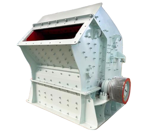
Reliable PFW Hydraulic Impact Crusher Machine
The PFW Series Impact Crusher is a new generation of high-efficiency equipment equipped with an advanced hydraulic control system. Its core advantages lie in the hydraulic system’s application, which significantly extends the service life of wear parts such as hammers and liners. Concurrently, it comprehensively enhances equipment operational stability, discharge particle size adjustment accuracy, and overload protection capability, achieving a breakthrough in overall performance.
Introduction
The PFW Series Impact Crusher is a new generation of high-efficiency equipment equipped with an advanced hydraulic control system. Its core advantages lie in the hydraulic system’s application, which significantly extends the service life of wear parts such as hammers and liners. Concurrently, it comprehensively enhances equipment operational stability, discharge particle size adjustment accuracy, and overload protection capability, achieving a breakthrough in overall performance.
Application
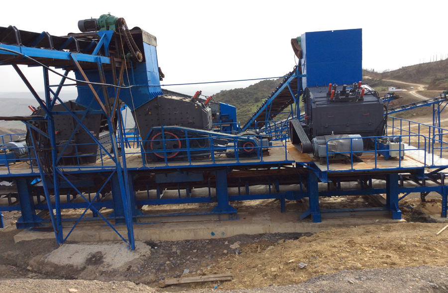
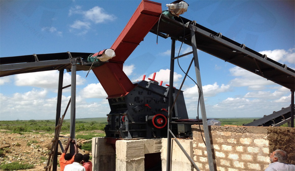
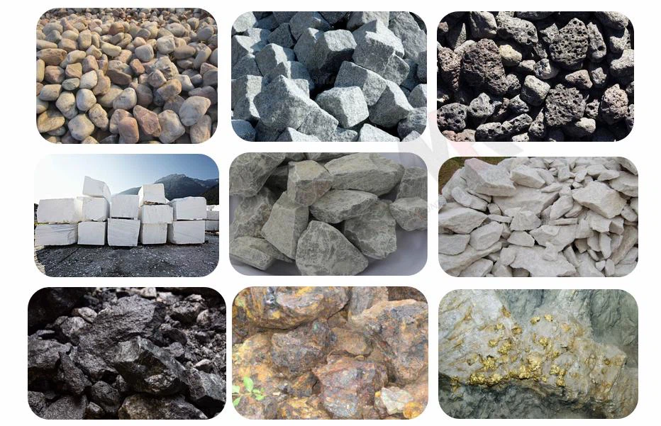
The PFW Series Impact Crusher is a high-efficiency crushing device specifically designed for medium and low-hardness materials. It excels at processing various mineral raw materials including limestone, calcite, gypsum, kaolin, talc, and graphite. With its superior crushing efficiency and particle shape control, it serves as a core piece of equipment in industrial sectors such as mining, metallurgy, building materials, and chemical engineering. It is also widely used in the production of sand and aggregate for infrastructure construction projects like highways and water conservancy projects.
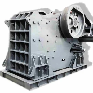
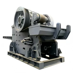
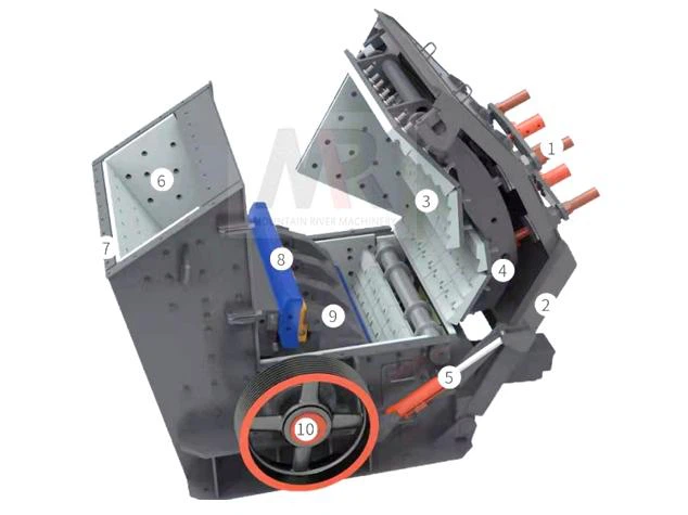
Main Structure
1. Hydraulic Adjustment Device | 2. Rack Liner | 3. Impact Liner | 4. Counter Rack |
5. Hydraulic Lifting Device | 6. Rack Liner | 7. Front Rack | 8. Blow Hammer |
9. Rotor | 10. Bearing Box |
Technical Parameters
Model | Rotor Specifications (mm) | Inlet Size (mm) | Feed Particle Size (mm) | Capacity (t/h) | Weight(t) |
PFW1214III | Φ1150×1400 | 570×1430 | <250 | 90-170 | 19 |
PFW1315III | Φ1300×1500 | 625×1530 | <300 | 180-270 | 25 |
PFW1318III | Φ1300×1800 | 625×1830 | <300 | 220-300 | 30 |
PFW1415III | Φ1400×1500 | 800×1530 | <350 | 250-350 | 32 |
PFW1214II | Φ1150×1400 | 1100×1430 | ≤500 | 130-200 | 22 |
PFW1315II | Φ1300×1500 | 1200×1530 | ≤600 | 180-320 | 29 |
PFW1318II | Φ1300×1800 | 1200×1830 | ≤700 | 240-400 | 34 |
PFW1415II | Φ1400×1500 | 1450×1530 | ≤800 | 260-450 | 36 |
Installation and Maintenance Recommendations
Installation Phase
The equipment must be installed on a reinforced concrete foundation specifically designed according to geological conditions and equipment load. High-performance vibration damping pads should be installed between the base and the foundation. After placement, strict leveling and drive alignment must be performed to ensure the equipment is stable and operates smoothly. Sufficient space for maintenance and material discharge must be reserved beneath the foundation.
Routine Maintenance Phase
Operators must check critical bolts, the hydraulic system, and belt condition, and perform manual rotation of the rotor before start-up. During operation, closely monitor vibration, noise, bearing temperature, and the working status of the hydraulic system. Stop the machine immediately upon detecting any abnormality. After shutdown, ensure all material is discharged and perform necessary cleaning and inspection.