

Raymond Mill Startup and Shutdown Sequence: Step-by-Step Procedure and Negative Pressure Operation Guide
What is the correct startup and shutdown sequence for a Raymond mill? A Raymond mill grinding circuit starts in this order: bucket elevator, jaw crusher (if fitted), classifier, induced-draft blower, main grinding chamber, then the feeder. The circuit shuts down in reverse: the feeder stops first, the main chamber runs empty for approximately one minute to clear residual material, the main motor stops, the blower stops next, and the classifier stops last. This order lets the negative-pressure airflow establish before material enters the grinding chamber, and it clears the chamber of dust before the draft is cut. Reversing the order — for example, cutting the blower before the feeder — allows material and dust to settle inside the mill housing and ductwork, which raises the risk of blockage and dust leakage at restart.
What You Will Learn from This Guide
This guide explains the mechanical logic behind the startup and shutdown order of a Raymond mill grinding circuit, the negative-pressure principle that keeps dust inside the ductwork during operation, and the monitoring steps an operator uses to confirm the circuit runs within its design pressure range. It serves two readers: an operator or maintenance planner standardizing a startup/shutdown work instruction for an existing installation, and a process engineer specifying a new grinding line who needs to define airflow and interlock requirements before writing a procurement inquiry. After reading this guide, you will be able to write a startup/shutdown checklist that sequences each machine correctly, recognize the pressure readings that signal a developing fault before it causes downtime, and describe a negative-pressure design point to a supplier instead of relying on a sales engineer’s summary.
Overview: What Fixes the Startup and Shutdown Order
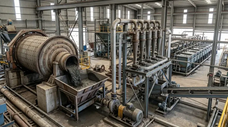
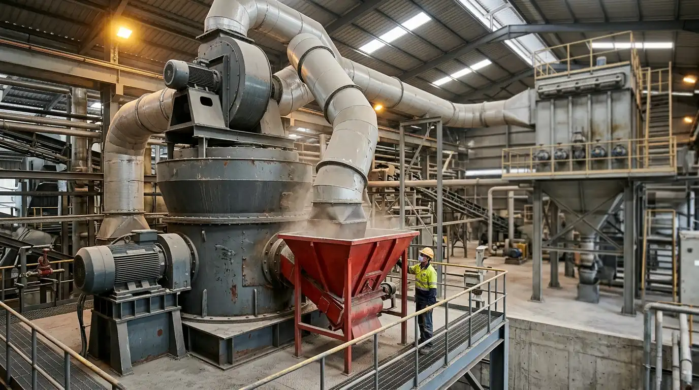
A Raymond mill grinding circuit is not one machine. It is a closed airflow loop built from an elevator, an optional pre-crusher, a classifier, a main grinding chamber, an induced-draft blower, a cyclone separator, and a bag filter. The MGW Intelligent Raymond Mill is one example of this circuit design, with the classifier and airflow controls integrated into the main housing.
Two mechanical constraints fix the sequence. First, the airflow must reach a stable negative pressure before feed material enters the grinding chamber, so that dust generated at the rollers is drawn into the duct instead of escaping through the feed inlet or seals. Second, the grinding chamber must be cleared of material before the airflow stops, so that residual powder does not sit inside the housing and cake onto the rollers and grinding ring during the idle period. These two constraints are the reason the feeder is always the last component to start and the first to stop.
Every material has a maximum in-feed rate, above which the negative-pressure system cannot clear dust at the rate it is generated. Operators size the feed rate to the mill’s air volume, not the reverse, which is why the feeder starts last and stops first in the sequence.
Main Components That Determine the Startup and Shutdown Order
The startup and shutdown order is determined by six components arranged in a closed loop, each documented in commissioning records for installations such as the 12 t/h Raymond mill installation for grinding barite.
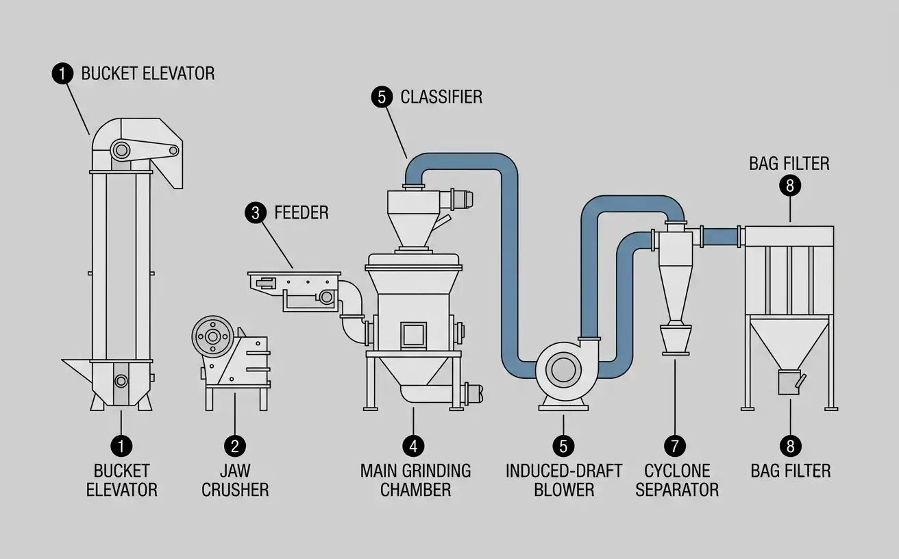
- Bucket elevator. Lifts crushed feed material to the mill’s storage hopper. It has no interaction with the airflow circuit and starts first because it has the longest travel time before material reaches the feeder.
- Jaw crusher (where fitted). Pre-crushes oversized feed to the particle size the mill accepts, typically below 30–50 mm depending on the model. It runs independently of the airflow loop.
- Classifier. A rotating vane assembly at the top of the grinding chamber that separates finished powder from oversized particles. Its blade speed sets the cut point of the finished product and must reach its set rotational speed before the blower increases airflow.
- Induced-draft blower. Draws air through the grinding chamber, classifier, cyclone, and bag filter, creating the pressure gradient that moves dust and finished powder through the circuit. It is the component that establishes negative pressure.
- Main grinding chamber. Houses the grinding rollers and ring. The main motor drives the roller assembly, which relies on centrifugal force to press the rollers against the ring.
- Feeder. Meters raw material into the grinding chamber. It starts only after the airflow and grinding elements are running at their operating point.
The next two sections apply this component order to the startup and shutdown procedures.
Step-by-Step Startup Procedure
Follow this sequence when starting a Raymond mill grinding circuit from a cold or idle state, following the same order documented in the commissioning record for the 12–13 t/h MGW175 Raymond mill for grinding calcium oxide. Confirm lubrication levels, belt tension, and that the grinding chamber is free of foreign objects before beginning.
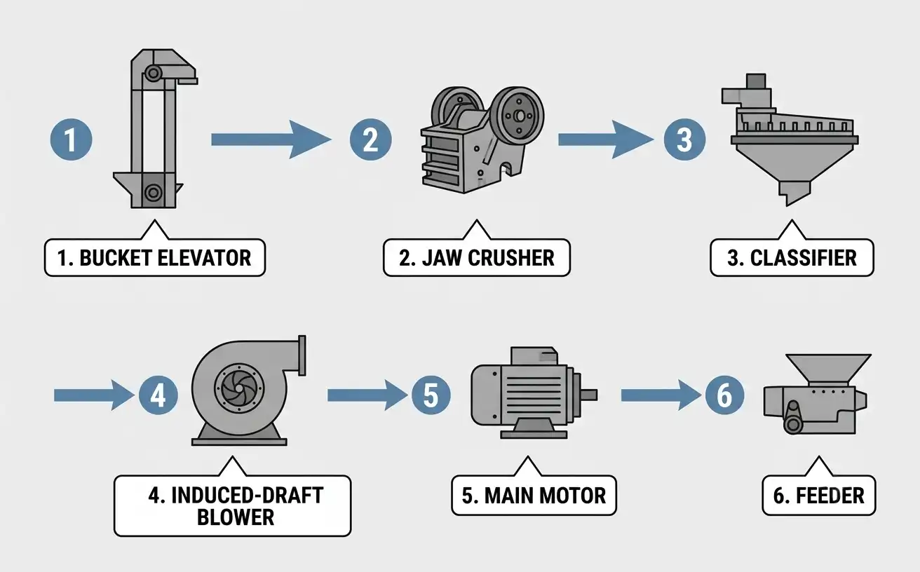
- Start the bucket elevator. Confirm the elevator runs without slippage or unusual noise before material is loaded onto it.
- Start the jaw crusher, if the circuit includes one. Allow it to reach full speed before feeding crushed rock into it.
- Start the classifier. Bring the classifier to its set operating speed. On mills with adjustable classifiers, this speed corresponds to the target product fineness and is set before the blower starts.
- Start the induced-draft blower. Open the inlet damper gradually until the blower reaches its rated current. Confirm the negative pressure gauge at the mill outlet shows a stable reading before proceeding.
- Start the main motor. Allow the grinding rollers to reach operating speed with no material in the chamber. Check for abnormal vibration or bearing temperature before feeding.
- Start the feeder within approximately two minutes of the main motor reaching operating speed. Increase the feed rate gradually while watching the main motor current; do not exceed the rated current shown on the motor nameplate.
On that calcium oxide line, feed moisture control adds a drying-air step before the feeder starts, applied after step 5 and before step 6 above.
Step-by-Step Shutdown Procedure
Shutdown reverses the startup order, following the pattern logged for the 7 t/h MGW138 Raymond mill for grinding bentonite. Stopping the components out of sequence — cutting the blower before the feeder, for example — leaves material and dust inside the grinding chamber and ductwork.
- Stop the feeder first. Cut off material in-feed while the main motor, blower, and classifier continue running.
- Let the main chamber run empty. Keep the main motor and blower running for approximately one minute after the feeder stops. This clears residual material from the grinding zone and prevents it from caking on the rollers and ring during the idle period.
- Stop the main motor. Confirm the rollers come to a full stop before proceeding to the next step.
- Stop the induced-draft blower, once residual dust in the ductwork has been drawn into the cyclone and bag filter. Close the inlet damper before stopping the blower motor to reduce back-draft through the system.
- Stop the classifier last. The classifier stops after the blower because residual fines in the classifier chamber continue to settle out under the classifier’s own airflow for a short period after the main draft is removed.
- Stop the bucket elevator and jaw crusher, if not already idle, once no material remains in transit.
That installation’s shutdown log shows this sequence extended to include a duct purge step, used on materials that generate fine, cohesive dust.
How Negative Pressure Operation Works in a Raymond Mill Circuit
Negative pressure works the same way in every air-swept circuit, including the finer classification loop on the MSF Ultrafine Grinding Mill: the induced-draft blower sits downstream of the grinding chamber, cyclone, and bag filter, and it pulls air through the circuit rather than pushing it. This arrangement puts nearly the entire circuit under negative pressure relative to the surrounding atmosphere, with one exception: the short duct segment between the blower outlet and the point where clean air re-enters, if the design recirculates air back to the mill inlet, runs at slightly positive pressure. Everywhere else — the grinding chamber, the classifier housing, the cyclone, and the ductwork leading to the bag filter — runs below atmospheric pressure. Because the pressure inside the equipment is lower than the pressure in the surrounding room, air leaks inward through any gap in a seal or duct joint, rather than dust leaking outward.
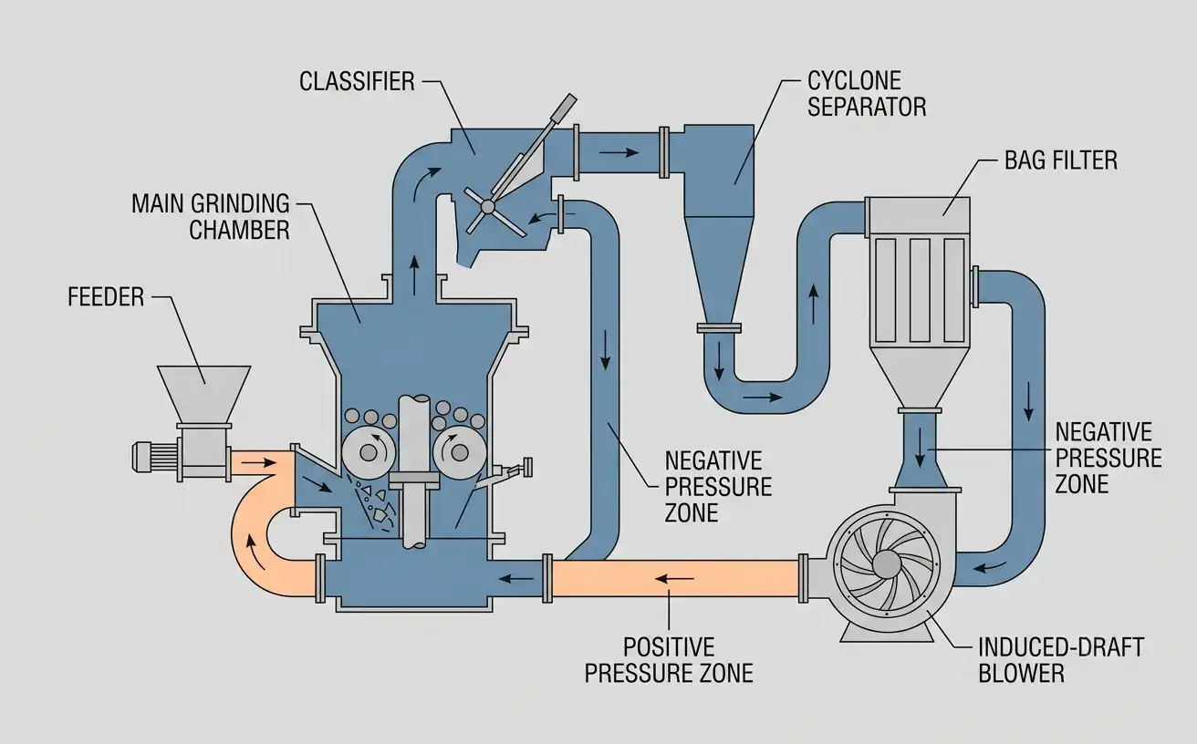
Feed moisture and material temperature both affect the air volume moving through the circuit. Moisture in the feed evaporates during grinding, which adds gas volume to the circuit and can push the system toward positive pressure if the excess is not vented. To hold the negative-pressure setpoint under these conditions, the circuit routes surplus air through a bleed duct into the bag filter before exhaust, rather than allowing it to accumulate inside the mill housing. On a finer classification cut, pressure control has a narrower tolerance band, because the product particles are smaller and more easily entrained in the airflow.
Monitoring and Adjusting Negative Pressure During Production
An operator checks negative pressure at two points during normal production — a routine documented for the 4–5 t/h Raymond mill for grinding petroleum coke: the damper at the mill’s air inlet and the damper at the outlet leading to the classifier. The inlet damper is normally set close to fully open to maximize airflow into the grinding chamber. The outlet damper is adjusted until no visible dust escapes at the feed inlet — closing it further increases the draft through the chamber, which also increases the proportion of fine material carried to the classifier and, in turn, tends to reduce the finished particle size for a given classifier speed.
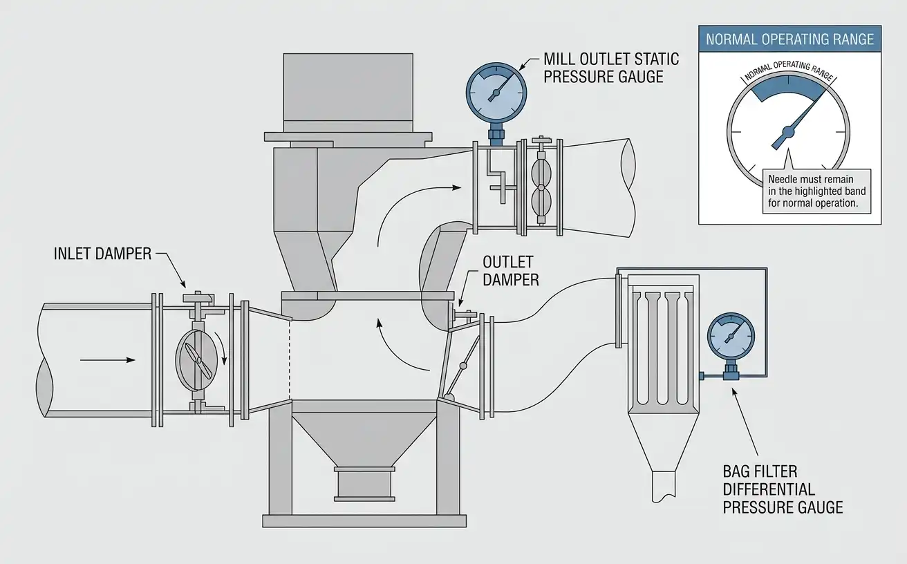
Two instruments confirm the system is within its operating range:
- Differential pressure gauge across the bag filter. Donaldson, a dust-collection equipment manufacturer, states that a typical operating assumption for fan selection is 4 to 5 inches of water gauge (in. wg) differential pressure across the filter media, with cartridge-style elements reaching a maximum of approximately 6.0 in. wg before cleaning can no longer restore filter capacity. A steady reading within this band indicates the filter media is loading and cleaning normally; a reading climbing past the manufacturer’s stated maximum indicates the filter needs cleaning or replacement before the draft fan is overloaded.
- Static pressure gauge at the mill outlet. This reading confirms the blower is maintaining draft through the grinding chamber. A falling reading, with the blower current unchanged, points to a duct leak or a partially blocked inlet screen rather than a filter problem.
Because the negative-pressure setpoint for a specific installation depends on duct length, material moisture, and classifier fineness setting, the operating pressure for a particular mill model and material combination is not a single universal number. That petroleum coke line used a narrower pressure band than a limestone line of the same model, because petroleum coke dust requires tighter containment. For a duty-point pressure specification on a specific material and throughput, request the commissioning data through a technical inquiry on the mill’s product page rather than applying a generic figure from an unrelated installation.
Raymond Mill vs Ball Mill: Sequencing and Pressure-System Differences
A Raymond mill and the MQ Ball Mill both grind material to a target particle size, but they use different airflow architectures, which changes how each machine is started, stopped, and monitored.
| Variable | Raymond Mill (Air-Swept) | Ball Mill (Closed-Circuit) |
|---|---|---|
| Airflow role | Airflow removes finished product from the grinding zone; negative pressure is required for normal operation | Airflow (if present) is limited to a separate drying or classifying loop; grinding itself does not depend on airflow |
| Startup sequence complexity | Six-step sequence tied to airflow establishment before feeding | Simpler sequence: lubrication system, then main motor, then feeder; no airflow interlock on the grinding action itself |
| Negative-pressure requirement | Required throughout operation to contain dust and convey product | Not applicable to the grinding chamber; may apply to an auxiliary drying circuit only |
| Typical feed moisture tolerance | Lower; excess moisture increases gas volume and disrupts pressure control | Higher; wet grinding is a standard ball mill configuration |
| Product fineness control | Set by classifier speed and airflow rate, adjustable without stopping the mill | Set by grinding media size and residence time, adjustable only by changing media charge |
Because ball mill grinding does not depend on an air-swept circuit, its startup sequence has no negative-pressure interlock step, though a ball mill used with an air classifier reintroduces a similar sequencing requirement for that auxiliary loop.
The airflow dependency is the variable most likely to drive the selection decision. A material with feed moisture above the mill’s rated tolerance, or a process requiring simultaneous drying and grinding, favors an air-swept Raymond mill despite its more involved startup sequence; a material ground wet, or a process without a drying requirement, removes the main advantage of the air-swept design.
Reference Values for Airflow and Dust-Control Components
The table below compiles published reference values relevant to Raymond mill negative-pressure operation. These figures come from general industrial dust-collection and occupational-exposure standards, not from a specific mill model, and are provided as a starting reference point rather than a design specification for any individual installation.
Reference parameters for negative-pressure and dust-control components in air-swept grinding circuits
| Parameter | Value | Unit | Condition / Test Method |
|---|---|---|---|
| Bag filter differential pressure, design assumption | 4–5 | in. wg | Typical fan-selection assumption for a bag-type dust collector |
| Cartridge filter differential pressure, maximum before cleaning ineffective | 6.0 (150 daPa) | in. wg | Ultra-Web® cartridge media, manufacturer-stated saturation point |
| Particulates not otherwise regulated (PNOR), total dust, 8-hour TWA | 15 | mg/m³ | OSHA Permissible Exposure Limit, 29 CFR 1910.1000 Table Z-3 |
| Particulates not otherwise regulated (PNOR), respirable fraction, 8-hour TWA | 5 | mg/m³ | OSHA Permissible Exposure Limit, 29 CFR 1910.1000 Table Z-3 |
| Raymond roller mill feed size, standard range | 0.5–2 (10–50) | in (mm) | Manufacturer equipment specification, air-swept vertical ring-roll design |
| Raymond roller mill finished product fineness, achievable range | 10% R2000 µm to 99.9% minus 325 mesh | — | Manufacturer equipment specification |
Source: values compiled from OSHA, Donaldson, and Qlar published technical references cited in Sources & References below; not derived from a single mill installation.
Data gap note. Site-specific negative pressure setpoints, static pressure loss per meter of duct, and bag-filter cleaning-cycle intervals for a particular Raymond mill model and material combination are not published in a general reference table because they depend on duct routing, material bulk density, and classifier fineness setting for that installation. Readers who need a duty-point specification for a defined throughput and material should request commissioning data through the manufacturer’s technical inquiry channel rather than apply the general values above directly.
Common Sequencing and Negative-Pressure Faults
The patterns below are drawn from field troubleshooting logs, including records from a 15–26 t/h Raymond mill for grinding fertilizers installation, and apply to most air-swept Raymond mill circuits regardless of material.
| Symptom | Probable Cause | Corrective Action |
|---|---|---|
| Dust visible at the feed inlet or seals during operation | Outlet damper open too far, reducing draft through the chamber; or a rotary airlock seal worn, allowing air to bypass the negative-pressure zone | Close the outlet damper incrementally until dust stops escaping; inspect and replace the rotary airlock seal if damper adjustment does not resolve it |
| Main motor current rising with blower current falling | Feed rate exceeds the airflow’s capacity to clear material, causing material buildup in the grinding chamber | Reduce the feed rate; confirm the blower inlet screen and ductwork are not partially blocked |
| Finished product coarser than the classifier setting | Classifier blade wear, or blower airflow reduced below its design point | Inspect classifier blades for wear; check blower belt tension and inlet damper position |
| Bag filter differential pressure above the manufacturer’s stated maximum | Filter media saturated with dust, or compressed-air cleaning system underperforming | Inspect the pulse-cleaning system’s air supply pressure; replace filter media if cleaning does not restore normal differential pressure |
| System pressure drops with no change in operating settings | Duct leak, damaged compensator, or loose flange joint downstream of the blower | Inspect ductwork joints and flexible compensators for tears or gaps; seal or replace as needed |
The main motor and blower current relationship in the table above is the fastest indicator available to an operator without opening the mill housing: when the two currents move in opposite directions, feed rate is the first variable to check, before inspecting internal components.
Preventive Maintenance Schedule for Airflow and Pressure Components
Scheduled inspection of the airflow and sealing components prevents most negative-pressure faults before they affect production. The MGW Intelligent Raymond Mill specifications list the rated airflow and classifier speed range that this schedule checks the system against.
- Daily: Record the bag filter differential pressure and the mill outlet static pressure at a fixed time each shift. Compare against the previous day’s reading rather than only against the design range, since a sudden shift often appears before the absolute value leaves the normal band.
- Weekly: Inspect the rotary airlock seal at the feeder and the discharge point for visible wear or dust leakage. Check compressed-air supply pressure to the bag filter’s pulse-cleaning system.
- Monthly: Inspect flexible duct compensators and flange gaskets along the full circuit for tears, gaps, or loose fasteners. Verify the classifier blade condition through the inspection port.
- Annually, or at the interval specified in the equipment manual: Replace bag filter media that has not recovered its rated differential pressure after cleaning. Inspect and, if worn, replace the blower impeller and rotary airlock rotor.
Frequently Asked Questions
What is the correct startup sequence for a Raymond mill?
The startup sequence is: bucket elevator, jaw crusher (if fitted), classifier, induced-draft blower, main motor, then feeder, as specified for the MGW Intelligent Raymond Mill and comparable air-swept models. The feeder starts last, typically within two minutes of the main motor reaching operating speed, so that negative pressure and grinding-roller speed are established before material enters the chamber.
Why does a Raymond mill stop the feeder before the main motor during shutdown?
Stopping the feeder first lets the main motor and blower continue running for approximately one minute, which clears residual material from the grinding chamber. If the main motor stops before the feeder, unground material remains inside the chamber and can cake onto the rollers and ring during the idle period.
What negative pressure value is normal for a Raymond mill dust collection system?
There is no single universal value; the correct operating pressure depends on duct length, material moisture, and the classifier’s fineness setting for the specific installation. A stable bag filter differential pressure in the 4–5 in. wg range, per typical dust-collector fan-selection assumptions, is a general starting reference, not a fixed target for every mill.
What causes dust to leak from a Raymond mill during operation?
Visible dust at the feed inlet or seals during operation is most often caused by the outlet damper being open too far, which reduces draft through the chamber, or by a worn rotary airlock seal that allows air to bypass the negative-pressure zone. Closing the outlet damper incrementally, and inspecting the airlock seal, resolves most cases.
How long should a Raymond mill run empty before shutdown?
The main motor and blower typically continue running for approximately one minute after the feeder stops, which clears residual material from the grinding zone before the main motor is switched off.
References & Sources
- OSHA Permissible Exposure Limits — Annotated Table Z-3, Particulates Not Otherwise Regulated
- Donaldson — What Is Differential Pressure? (Industrial Dust, Fume & Mist Technical Articles)
- NIOSH Pocket Guide to Chemical Hazards — Particulates Not Otherwise Regulated
- Qlar — Raymond Roller Mill, Air-Swept Vertical Ring-Roll Technology