

Raymond Mill Roller and Ring Uneven Wear: Root Causes and Spring Tension Adjustment
Why do a Raymond mill’s grinding roller and ring wear unevenly, and how is it corrected? Uneven, one-sided wear on a Raymond mill’s grinding roller or ring almost always traces back to one of seven mechanical causes: unequal spring compression between pendulums, a roller bearing that has stopped rotating freely, loose roller-assembly fasteners, grinding-ring run-out, worn or flat shovel geometry, uneven feed distribution across the chamber, or feed material harder than the mill’s design rating. Spring tension adjustment corrects only the first of these — it equalizes the compressed length of every pendulum’s spring so each roller presses against the ring with matched, constant force. A high-pressure suspension mill typically carries a spring preload in the 1,000–1,500 kg range, contributing roughly 800–1,200 kgf of additional grinding force per roller. Adjusting the spring will not fix wear caused by a seized bearing, a bent shovel, or an out-of-round ring; those require parts replacement or realignment. The diagnostic table and procedure below walk through how to tell these causes apart before touching a wrench.
What You Will Learn from This Guide
This guide explains how to recognize the wear pattern that signals uneven roller-and-ring contact on a Raymond mill, work through a structured root-cause checklist, and correct spring-related imbalance without disturbing causes that spring adjustment cannot fix. It is written for the maintenance engineer or mill operator responsible for scheduled inspections and mid-life corrective work, not for a buyer evaluating equipment for the first time. You will find the mechanics of the spring-loaded pressure system, a step-by-step spring tension equalization procedure, the pressure and wear-life figures published in OEM engineering documentation and patent literature, and a preventive inspection schedule sized to real operating hours. After reading this guide, you will be able to distinguish spring-related uneven wear from bearing-, ring-, shovel-, or feed-related wear, and select the correction that actually addresses the cause instead of defaulting to a spring adjustment that will not hold.
Recognizing Uneven Grinding Roller and Ring Wear
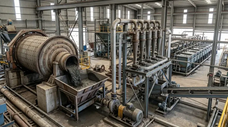
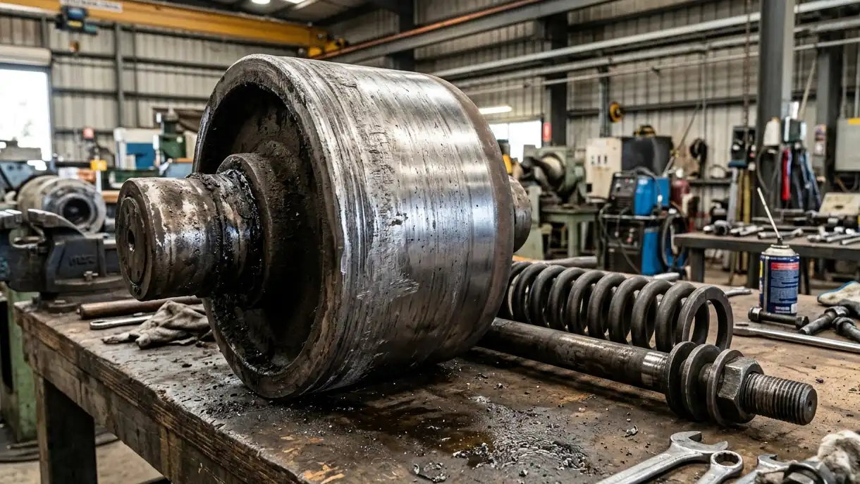
A new grinding roller on a MGW Intelligent Raymond Mill or any comparable pendulum-type Raymond mill has a uniformly cylindrical contact face. Uneven wear shows up first as a taper or a concave dip across that face, paired with a matching wear band on the grinding ring at the same height. The roller no longer contacts the ring along a straight line; contact narrows to one edge or one section of the circumference, and the local contact pressure at that narrow band rises well above the design value even though the spring load has not changed. Operators typically notice the problem indirectly before they see it directly: output fineness becomes inconsistent between batches, iron content in the product edges up as metal-to-metal contact increases, and vibration at the mill housing grows louder over a period of weeks rather than appearing suddenly. A field technician who pulls the access panel at that point usually finds a roller face that is visibly out of round or a ring segment with a groove cut deeper on one side than the other.
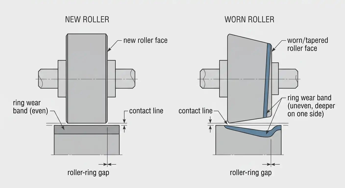
The wear pattern itself is a diagnostic clue, not just a symptom. A shallow, even taper across the full roller width points toward a load problem — most often the spring. A narrow, deep groove confined to the center of the roller face points toward the shovel or feed distribution instead. A rough, rippled surface with visible pitting suggests the roller has stopped rotating freely and is being dragged rather than rolled against the ring. Reading the shape correctly before adjusting anything saves a wasted spring reset on a mill where the spring was never the problem — see the 7 t/h Raymond mill installation grinding bentonite for an example of a commissioning record where roller wear pattern was logged against feed conditions from startup.
Seven Root Causes of One-Sided Roller and Ring Wear
Uneven wear on a Raymond mill has a limited number of mechanical origins, and each leaves a distinguishable pattern. Field technicians who skip the diagnostic step and go straight to spring adjustment fix the roughly one-in-seven cases where the spring actually is the culprit and leave the rest unresolved — the wear returns within weeks because the real cause was never addressed. The table below maps the wear pattern and equipment behavior to the underlying cause and the check that confirms it; see the 12–13 t/h Raymond mill case grinding calcium oxide for a record of several of these checks applied during a single service visit.
Table: Uneven Wear Diagnostic Reference
| Symptom Pattern | Likely Root Cause | Diagnostic Check |
|---|---|---|
| Uniform taper across all rollers; ring wear band shifted toward one edge | Unequal spring compression between pendulums | Measure and compare each spring’s compressed length and tie-rod nut position across all pendulums |
| Concave, rippled wear on one roller face with a matching groove in the ring | Roller bearing no longer rotating freely | Rotate the roller by hand after opening the housing; check bearing temperature and grease condition |
| Roller sits at a visible angle to the ring; wear concentrated on one edge of the face | Loose roller-assembly connecting bolts or nuts | Check torque on roller-hanger and cross-arm shaft fasteners against the OEM specification |
| Ring wear deeper on one side of the circumference, with matching roller wear | Grinding-ring run-out or axial play | Measure radial run-out and axial play with a dial indicator |
| Wear concentrated in a narrow band at the center of the roller and ring | Worn or flat-profile shovel geometry | Inspect shovel-to-roller clearance (target 2–3 mm) and blade curvature |
| One or two rollers wear faster than the others on the same shaft | Uneven feed distribution across the grinding chamber | Check feeder chute alignment and confirm material spreads evenly across the ring |
| All rollers show accelerated wear within a short operating period | Feed hardness exceeds the mill’s design rating | Verify feed Mohs hardness against the mill’s rated hardness range |
The single most common cause a technician can correct without replacing parts is the first row: unequal spring compression. The remaining six require either a mechanical repair — re-torquing fasteners, replacing a bearing, correcting ring run-out, adjusting or replacing a shovel — or a process change to feed handling. None of those six will improve by turning a tie-rod nut, and forcing a spring reset onto a mill with a seized bearing or a misaligned ring only adds load to an already-damaged component.
Why Spring Imbalance Is the Most Common Correctable Cause
A Raymond mill’s pendulum rollers hang from a cross-arm shaft on a rotating frame. Centrifugal force swings each roller outward against the grinding ring, and a compression spring mounted on the outer end of the pendulum adds force beyond what centrifugal action alone provides, using the cross-arm shaft as a lever fulcrum. If the springs on different pendulums are compressed to different lengths — because one was reset during a previous repair and the others were not, or because springs age and relax at slightly different rates — the rollers no longer press against the ring with equal force. The roller under the shortest, most compressed spring carries more of the total grinding load, wears faster, and develops the taper pattern described above. This is a load-distribution problem, not a material or lubrication problem, which is why it responds to spring adjustment and the other six causes in the table do not.
How the Spring-Loaded Pressure System Works
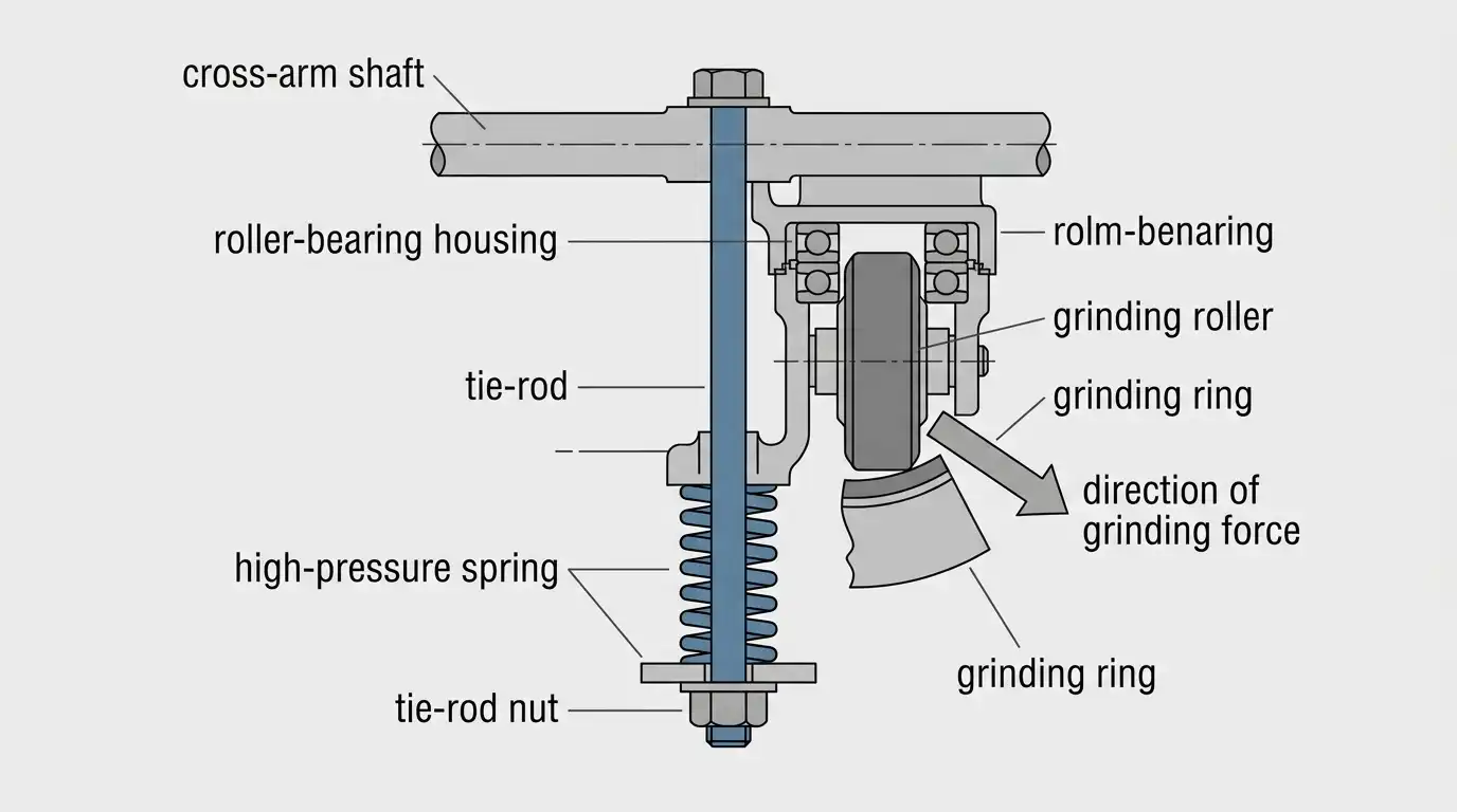
Before adjusting anything, it helps to understand what the spring is actually doing mechanically. The roller hangs from the cross-arm shaft, and a tie-rod runs from the roller-bearing housing, through the spring, to a nut on the outer end of the pendulum frame. Turning that nut changes the spring’s compressed length, which changes the force the spring transmits back through the tie-rod to the roller housing, which changes how hard the roller presses against the grinding ring. On a high-pressure suspension mill, the spring preload typically falls in the 1,000–1,500 kg range and adds roughly 800–1,200 kgf of grinding force to each roller beyond what centrifugal swing alone would produce — figures reported across published OEM engineering documentation for this mill category. The tie-rod and spring assembly also functions as an overload protection device: if a tramp object or an oversized lump enters the grinding chamber, the spring compresses further and lets the roller move outward momentarily rather than transmitting a shock load through the drive train. See the 15–26 t/h Raymond mill case grinding fertilizer for a commissioning example where spring preload was set and verified before the mill was handed over for continuous operation.
Because every pendulum on the mill uses the same tie-rod-and-spring arrangement, the mill’s design intent is for all rollers to apply equal pressure. A mill with three, four, or six pendulums needs all three, four, or six springs matched to the same compressed length; a single pendulum reset without checking the others defeats that intent rather than restoring it. This is the mechanical basis for the equalization procedure in the next section, and it is the reason the procedure treats every pendulum as one measurement in a set rather than an isolated adjustment — see the 4–5 t/h Raymond mill case grinding petroleum coke for a related service record involving spring-set verification across all pendulums during a scheduled overhaul.
Step-by-Step Spring Tension Equalization Procedure
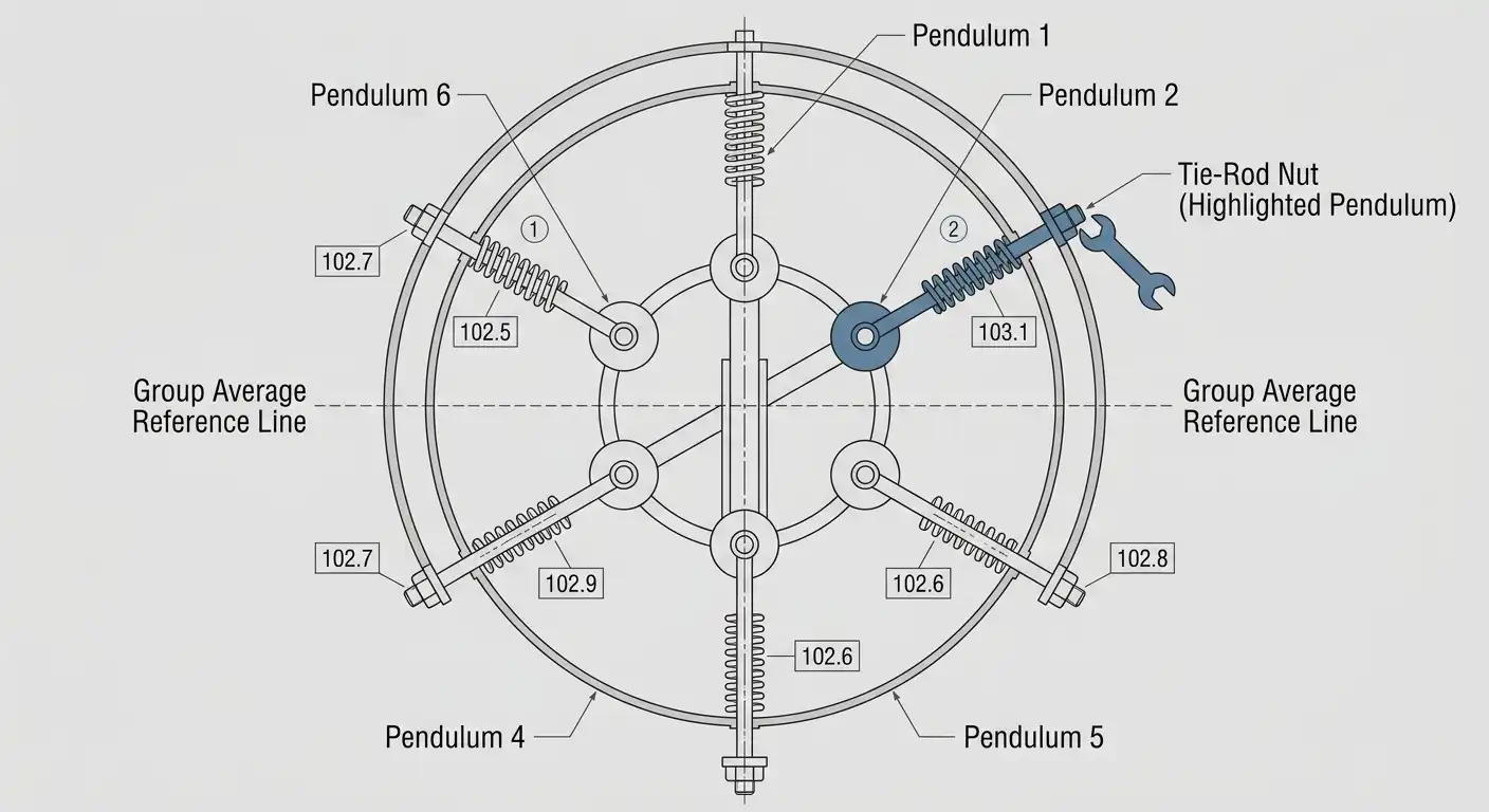
Confirm through the diagnostic table above that spring imbalance, not bearing seizure, loose fasteners, ring run-out, shovel wear, feed distribution, or feed hardness, is the cause before starting this procedure. Adjusting spring tension on a mill with one of the other six problems will not correct the wear pattern and can mask a developing bearing or ring failure. Refer also to the 12 t/h Raymond mill case grinding barite for an example of this sequence applied to a six-pendulum mill during a routine service interval.
- Stop the mill and lock out the main drive per the site’s lockout/tagout procedure before opening any pendulum access panel.
- Confirm the mill has come to a complete stop and verify zero energy state before working near any roller or spring assembly.
- Open the access panel for each pendulum and inspect the roller by hand for play, uneven rotation resistance, or visible tilt relative to the ring.
- Measure the compressed length of each pendulum’s spring with the tie-rod nut in its current position, and record the value for every pendulum on the mill.
- Compare the recorded lengths across all pendulums, and identify which springs sit shorter (over-compressed, higher force) or longer (under-compressed, lower force) than the group average.
- Loosen the tie-rod locknut on any pendulum whose spring length deviates from the group average.
- Turn the tie-rod nut to bring the spring to the target compressed length specified in the mill’s OEM manual, or to the average of the other pendulums if no OEM value is available.
- Re-torque the tie-rod locknut once the target length is reached, and record the final measurement in the maintenance log.
- Repeat steps 4 through 8 for every remaining pendulum before restarting the mill; a partial adjustment that corrects some pendulums and leaves others untouched reintroduces the same imbalance in a different location.
- Restart the mill under reduced feed rate first, and monitor vibration and product fineness for at least one full production cycle before returning to full feed.
The exact target compressed length and the tie-rod torque specification vary by roller diameter and OEM design, and general technical literature does not publish a single universal figure for either one. Confirm both against the mill’s OEM manual or nameplate data, or request the specification through the manufacturer’s technical support channel if the manual is unavailable — matching every pendulum to the same measured value, even without the OEM target, restores even loading and stops the wear from progressing while the correct figure is sourced.
Published Grinding Pressure Ranges and Wear-Life Benchmarks
The figures below are compiled from published OEM engineering documentation for high-pressure suspension and Raymond-type roller mills. They provide a reference range for planning inspections and evaluating whether a mill’s measured values fall within a normal band, not a substitute for the specific mill’s own OEM data.
Table: Typical Spring Pressure and Wear-Life Parameters
| Parameter | Typical Value | Unit | Condition / Basis |
|---|---|---|---|
| High-pressure spring preload | 1,000–1,500 | kg | High-pressure suspension mill design, varies by roller diameter and OEM |
| Added grinding force from spring loading | 800–1,200 | kgf | Same design category, force added beyond centrifugal swing alone |
| Roller diameter wear-replacement threshold | ~5 | % reduction from new diameter | General guidance; confirm against the specific model’s OEM tolerance |
| Roller and ring service life, moderate-hardness feed | 2,000–3,000 | operating hours | Feed such as limestone or barite; shorter for harder feed such as quartz |
| Roller bearing inspection interval | ~500 | operating hours | Lubrication condition and free-rotation check |
Values in this range vary by roller diameter, spring design, and duty cycle, and the exact target spring compression distance and tie-rod torque are model-specific figures that general technical literature does not publish. A mill running a harder feed material, a coarser feed top size, or a longer duty cycle between shutdowns will sit at the lower end of the roller-life range regardless of how well the spring tension is maintained; the spring adjustment procedure controls load distribution between rollers, not the total wear rate driven by the feed material itself. See the 7 t/h Raymond mill installation grinding bentonite and the 1.5–2 t/h Raymond mill case grinding alumina for two documented installations at different feed hardness levels, useful for comparing where a given feed material is likely to land within the service-life range above. If a specific mill’s recorded roller life falls well outside this range in either direction, that gap is itself worth investigating — either the feed material differs from what the range assumes, or a root cause from the diagnostic table is shortening life faster than normal.
Preventive Maintenance Schedule to Limit Uneven Wear
Most uneven-wear cases are preventable with an inspection schedule that catches spring drift, bearing wear, and fastener loosening before they produce a visible taper. The intervals below assume moderate-hardness feed and standard duty cycles; adjust downward for harder feed or continuous three-shift operation. See the 15–26 t/h Raymond mill case grinding fertilizer for an example maintenance log structured around a comparable inspection interval.
Table: Preventive Inspection Schedule
| Task | Interval | What to Check |
|---|---|---|
| Visual roller and ring wear inspection | Every 500 operating hours | Roller diameter, ring wear band width and depth |
| Spring compression comparison across all pendulums | Every 500 operating hours | Compressed spring length per pendulum against the group average |
| Roller bearing lubrication and free-rotation check | Every 500 operating hours | Grease condition, bearing temperature, manual rotation test |
| Roller-hanger and cross-arm fastener torque check | Every 1,000–2,000 operating hours | Torque against OEM specification |
| Ring run-out and axial play measurement | Every 2,000 operating hours or at scheduled overhaul | Dial indicator radial and axial reading |
| Shovel and blade clearance and geometry inspection | Every 1,000 operating hours | Shovel-to-roller clearance (target 2–3 mm), blade wear and curvature |
The spring compression check and the bearing free-rotation check drive the largest share of preventable failures on this schedule, because both conditions develop gradually and produce no immediate change in output — a mill can run for weeks with a partially seized bearing or a drifted spring before vibration or fineness variation becomes noticeable. Scheduling both checks at the same 500-hour interval as the visual inspection catches the two conditions responsible for most of the uneven-wear cases documented in the diagnostic table above, before the wear pattern becomes severe enough to require part replacement. See the 4–5 t/h Raymond mill case grinding petroleum coke for a documented case where a 500-hour inspection interval caught early-stage bearing drag before roller replacement became necessary.
Matched-Set Replacement and When Chronic Wear Signals a Different Solution
Replacing a single worn roller while leaving the others in service reintroduces the same load-distribution problem the spring equalization procedure is meant to solve, because a new roller has a larger effective diameter than its worn neighbors and will contact the ring differently until the whole set wears back into alignment. For this reason, rollers on a given mill are typically replaced as a matched set rather than one at a time, even when only one shows advanced wear; the added parts cost is weighed against the labor cost of a second shutdown a few months later when an adjacent roller reaches the same wear limit on its own schedule.
A mill that develops uneven wear repeatedly despite correct spring maintenance, tight fasteners, and true-running rings is telling the operator something about the process rather than the machine: the feed material is likely too hard, too abrasive, or too variable for a spring-loaded pendulum design at the required throughput. In that scenario, an MSF Ultrafine Grinding Mill or a comparable ring-roller design with a different wear-part geometry may hold tolerance longer on the same feed, and for very hard or highly abrasive feed a MQ Ball Mill removes the roller-and-ring line-contact wear mechanism entirely by grinding through media impact instead of rolling contact. Neither substitution is automatic — output fineness, throughput, and energy consumption per ton differ between the three designs, and the decision should follow a review of the specific feed material rather than a general preference for one mill type over another.
Frequently Asked Questions
Why does one grinding roller in a Raymond mill wear faster than the others?
The most common cause is unequal spring compression between pendulums, which puts more grinding load on the roller under the shortest (most compressed) spring. Other causes include a bearing that has stopped rotating freely, loose roller-hanger fasteners, or uneven feed distribution reaching that roller’s section of the ring.
How do you adjust the spring tension on a Raymond mill grinding roller?
Lock out the mill, measure the compressed length of every pendulum’s spring, and reset the tie-rod nut on any spring that deviates from the group average so all springs reach the same compressed length. Adjust every pendulum in the same service visit rather than one at a time to avoid shifting the imbalance to a different roller.
When should you replace the grinding roller and grinding ring?
Replace them when the roller diameter has worn down by approximately 5% from new, or sooner if the wear pattern is uneven enough to affect grinding contact across the roller face. Confirm the exact tolerance against the specific mill’s OEM specification, since the replacement threshold varies by model.
Can uneven roller wear cause vibration in a Raymond mill?
Yes. A roller and ring that no longer contact along a straight line create an unbalanced load that shows up as increasing vibration at the mill housing over a period of weeks, along with inconsistent product fineness and rising iron content from the increased metal-to-metal contact.
Should Raymond mill rollers be replaced in matched sets?
Generally yes. Replacing a single roller introduces a diameter mismatch against the remaining worn rollers, which recreates an uneven-load condition until the new roller wears down to match the others. Matched-set replacement avoids that transitional imbalance.
References & Sources
- US Patent US3881348A — Hydraulic Spring Adjusting Device for Bowl Mills
- US Patent US7832665 — Tension Adjustment Gauge System and Method for Ball and Ring Coal Pulverizer
- Lu, Yao, Yao, Meng, Li & Shi — “Research of grinding efficiency and main duct wear of pendulum mill based on CFD-DEM co-simulation,” Advances in Mechanical Engineering (SAGE)
- ASTM E11 — Standard Specification for Woven Wire Test Sieve Cloth and Test Sieves