

How a Raymond Mill Works: Grinding Roller, Grinding Ring, and Pendulum Suspension Structure Explained
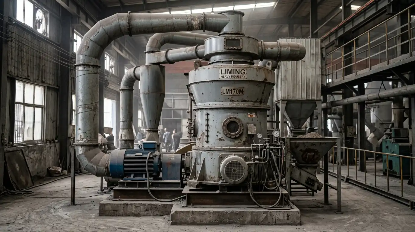
How does a Raymond mill work? A Raymond mill grinds material through a set of grinding rollers that hang from a rotating spider assembly and swing outward under centrifugal force to press against a stationary grinding ring. A blade system lifts feed material from the mill floor into the gap between the rollers and the ring, where compression and friction reduce particle size. An airflow generated by a fan carries the ground powder to a classifier, which returns oversized particles for further grinding and sends qualified fines to a dust collector. The whole grinding, classifying, and collecting sequence runs as a closed, negative-pressure circuit, which is why the machine also functions as an integrated dryer for feed material with moisture content below approximately 6%.
What You Will Learn from This Guide
This guide explains the mechanical working principle of a Raymond mill, with a specific focus on the three components that define how the machine reduces particle size: the grinding roller, the grinding ring, and the pendulum suspension structure that connects them. It serves an engineer or procurement specialist at the stage of comparing grinding technologies or writing a technical specification for a mill inquiry, before final vendor selection. After reading this guide, you will be able to identify which Raymond mill model class fits a given feed material and target fineness, read a Raymond mill specification sheet without relying on a sales engineer’s interpretation, and recognize the operating conditions under which a Raymond mill is not the correct equipment choice.
Overview
A Raymond mill is a vertical, air-swept grinding mill that combines size reduction, classification, and drying in a single machine. The design traces back to the late 19th century and is now built by manufacturers worldwide under names that include “Raymond mill,” “pendulum mill,” and “suspension roller mill.” All three names describe the same core mechanism: rollers suspended from a rotating frame press outward against a ring under centrifugal force.
The MGW Intelligent Raymond Mill is a current-generation example of this equipment class. According to the manufacturer’s product specification, the mill processes non-flammable, non-explosive minerals with a Mohs hardness below 9 and a moisture content below 6%, producing a finished powder in the 80 to 400 mesh range. The mill is built in five frame sizes, from the MGW110 to the MGW215, covering a rated capacity range of 3.5 to 45 t/h.
Raymond mills are not the correct equipment for every grinding task. A rotary ball mill handles wet grinding, higher-hardness feed, and applications where iron contamination from steel media is not a concern, in circumstances where a Raymond mill’s dry, roller-on-ring contact does not apply. A jet mill or ultrafine vertical mill produces output finer than 325 mesh more consistently than a standard Raymond mill, whose classifier design targets the 80 to 400 mesh window. The sections below state these boundaries explicitly rather than only listing the conditions favorable to Raymond mill technology.
Working Principle
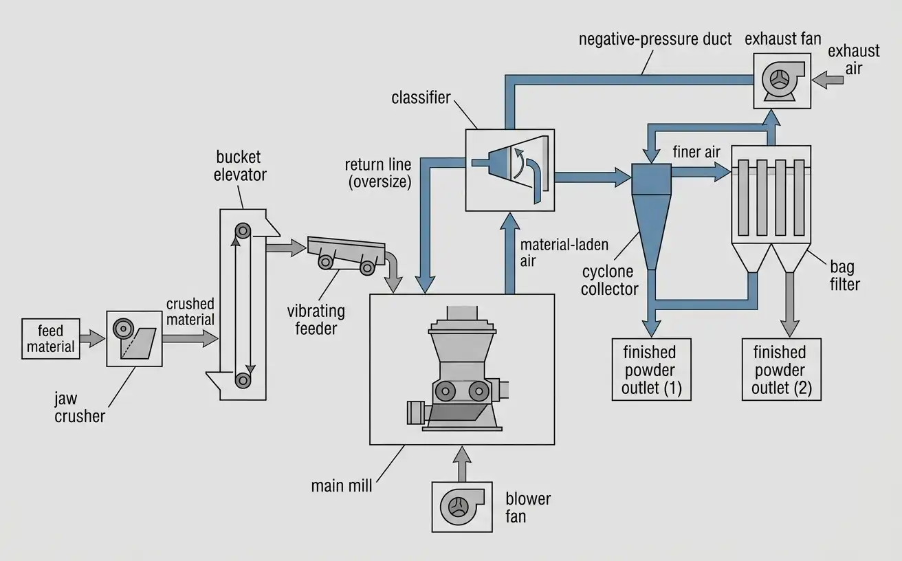
A Raymond mill reduces particle size in four sequential stages: feeding, grinding, classification, and collection. The PE Jaw Crusher or an equivalent primary crusher normally precedes the mill in a complete grinding line, since the main mill itself accepts only pre-crushed feed.
Feeding Stage
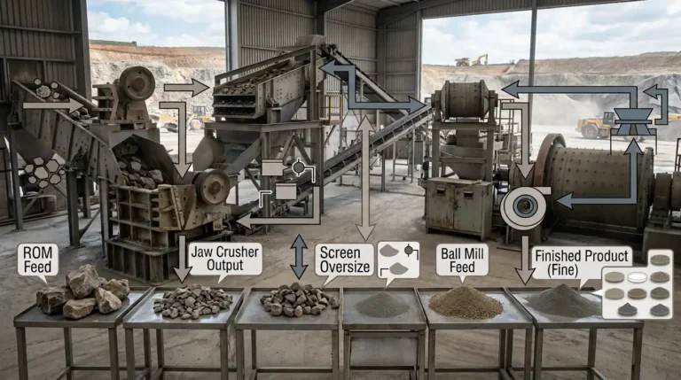
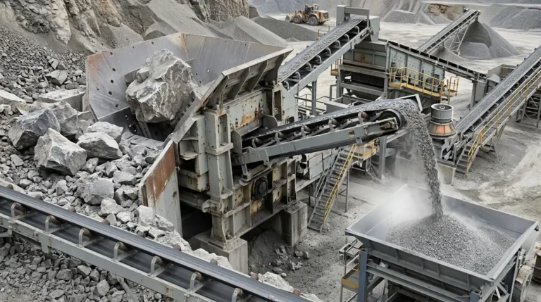
Raw material enters the circuit at a jaw crusher, which reduces lump feed to a size smaller than 20 mm before the material proceeds further. A bucket elevator lifts the crushed material to a hopper positioned above the main mill. A vibrating feeder then meters the material from the hopper into the mill at a controlled, continuous rate, which keeps the grinding chamber loaded within its designed operating range and avoids the surging that occurs with batch feeding.
Grinding Stage: Grinding Roller, Grinding Ring, and Pendulum Suspension Mechanics
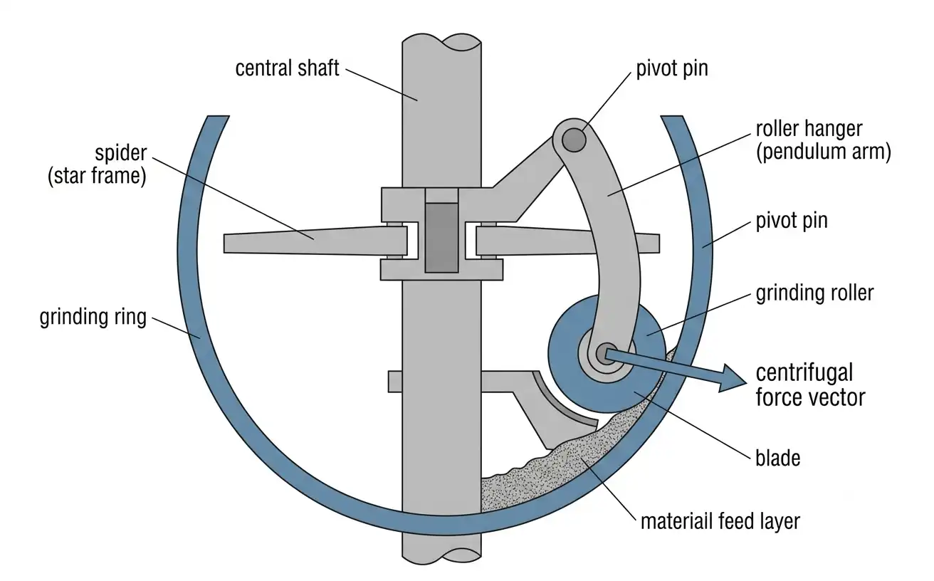
The grinding chamber contains three components that work together: the grinding roller, the grinding ring, and the pendulum suspension structure that connects the two. A central vertical shaft rotates a spider, also called a star frame, at the top of the grinding chamber. A roller hanger, functioning as a pendulum arm, hangs from a pivot pin on the spider. A grinding roller is mounted at the lower end of each roller hanger.
As the spider rotates, each roller hanger swings outward under centrifugal force, the same mechanical principle that swings a pendulum outward when its pivot point moves in a circle. This outward swing presses the grinding roller against the inner surface of the stationary grinding ring. The grinding ring does not rotate; it is fixed to the mill housing and functions as the counter-surface against which the roller compresses the material. The pendulum geometry means that grinding force is a direct function of shaft rotational speed: increasing the rotational speed increases centrifugal force and, in turn, increases roller-to-ring contact pressure, within the mechanical limits of the roller hanger and pivot assembly.
A blade, mounted on a blade base below the roller hanger, rotates with the assembly and lifts material from the floor of the grinding chamber into the gap between the roller and the ring. The material is compressed and sheared as the roller rolls over it against the ring surface, which reduces particle size through a combination of crushing and grinding action. The roller itself is not driven directly; it rotates around its own axis because of friction contact with the ring, in addition to revolving around the central shaft with the spider.
Grinding rollers and grinding rings are wear parts. Manufacturers commonly cast these components from high-manganese austenitic steel, a material family covered by ASTM A128/A128M, chosen for its work-hardening property: the surface hardens under impact and abrasive load during operation, which increases wear resistance progressively as the part is used, compared to a pre-hardened alloy that does not harden further in service.
Classification Stage
Ground material does not pass through the mill as a single output stream. Airflow generated at the bottom of the grinding chamber lifts the fine powder produced by the roller-ring grinding action upward to a classifier mounted above the grinding chamber. The classifier separates the powder by particle size using a rotating cage or vane wheel: fine particles that meet the target size pass through, while coarse particles are rejected and fall back into the grinding chamber for further passes between the roller and the ring. This closed-loop classification is what allows a Raymond mill to hold a consistent fineness target rather than producing a single uncontrolled particle-size distribution.
Collection Stage
Qualified fine powder leaving the classifier travels by airflow to a cyclone collector, where the powder separates from the air stream by centrifugal settling, and then to a bag filter (baghouse) for final dust capture before the air exhausts through the fan. The entire circuit, from the grinding chamber through the classifier and into the collection equipment, operates under negative pressure, so dust does not escape from the system into the surrounding work area. This closed-circuit design is also what allows the Raymond mill to dry moist feed material during grinding, since the airflow that carries the ground powder also carries off surface moisture, within the manufacturer’s stated 6% moisture limit.
Types and Model Comparison
Raymond mills are built in a range of frame sizes, distinguished primarily by grinding ring diameter, roller count, and installed motor power. The table below lists the technical specifications published by the manufacturer for the MGW Intelligent Raymond Mill series.
Table 1. MGW Intelligent Raymond Mill technical specifications by model
| Parameter | MGW110 | MGW138 | MGW175 | MGW198 | MGW215 |
|---|---|---|---|---|---|
| Grinding rollers (count) | 4 | 4 | 5 | 5 | 5 |
| Roller diameter × height (mm) | 640 × 320 | 460 × 240 | 520 × 280 | 620 × 300 | 640 × 320 |
| Grinding ring inside diameter × height (mm) | 1,100 × 190 | 1,380 × 240 | 1,750 × 280 | 1,980 × 300 | 2,150 × 320 |
| Maximum feed size (mm) | < 30 | < 35 | < 40 | < 50 | < 50 |
| Finished product size range (mm) | 1.6–0.038 | 1.6–0.038 | 1.6–0.038 | 1.6–0.038 | 1.6–0.038 |
| Capacity (t/h) | 3.5–10 | 6.5–15 | 13–20 | 15–30 | 30–45 |
| Main mill motor (kW) | 55 | 110 | 185 | 280 | 180 |
| Classifier motor (kW) | 11 | 18.5 | 37 | 55 | 90 |
| Fan motor (kW) | 55 | 110 | 200 | 280 | 315 |
Source: MGW Intelligent Raymond Mill manufacturer technical specification sheet.
Capacity is the parameter that most commonly drives model selection, and capacity does not scale linearly with grinding ring diameter across this series because roller count, roller dimensions, and motor power all change between models. A processing line rated for 15 t/h could be served by either the MGW175 (13–20 t/h rated range) or the MGW198 (15–30 t/h rated range); the choice between the two depends on whether future capacity expansion within the same footprint is a project requirement, since the MGW198 carries higher headroom above 15 t/h.
For material harder than Mohs 9, higher moisture content than 6%, or a wet-grinding process, the MQ Ball Mill is a different grinding technology within the same product line, using steel grinding media inside a rotating drum rather than a roller-on-ring mechanism. For target fineness beyond 400 mesh, the MSF Ultrafine Grinding Mill uses a different classifier design intended for that finer output range; a standard Raymond mill classifier is not optimized to hold a consistent particle size distribution above 400 mesh.
Specifications and Parameters
Fineness in Raymond mill technical literature is commonly expressed in mesh, a sieve-based unit standardized internationally under ISO 565 and, in the United States, under ASTM E11. Table 2 converts the mesh values referenced throughout this guide to micrometers for readers working in metric particle-size specifications.
Table 2. Mesh-to-micrometer conversion for common Raymond mill fineness targets
| Mesh (US/Tyler) | Approximate opening (µm) | Approximate opening (mm) |
|---|---|---|
| 80 | 180 | 0.180 |
| 100 | 150 | 0.150 |
| 150 | 106 | 0.106 |
| 200 | 75 | 0.075 |
| 250 | 63 | 0.063 |
| 325 | 45 | 0.045 |
| 400 | 38 | 0.038 |
Source: standard mesh-to-micrometer values per ISO 565 and ASTM E11 sieve specifications.
The 400-mesh figure (38 µm) is the lower boundary the MGW series is rated for; achieving output at or near this boundary requires the classifier to operate at higher rotational speed, which reduces net throughput compared to running the same mill at 200 mesh. This trade-off between fineness and throughput is why manufacturers publish a capacity range rather than a single fixed t/h figure for each model.
The MGW series product specification lists a Mohs hardness limit below 9 and a feed moisture limit below 6%. Feed hardness above Mohs 7 (the hardness of quartz) increases the abrasive wear rate on the grinding roller and grinding ring beyond the wear rate typical of softer carbonate or sulfate minerals such as calcite or barite, because higher-hardness feed particles cut into the wear-part surface more aggressively during each roller pass. A specification sheet for a Raymond mill inquiry should state feed Mohs hardness, feed moisture content, maximum feed lump size, and target mesh with an associated sieve pass rate (commonly expressed as D90, the particle size below which 90% of the sample’s mass falls), since these four values determine which frame size and classifier configuration the mill requires.
Selection Criteria
Model selection for a Raymond mill starts from three inputs: required capacity (t/h), target fineness (mesh, with a stated D90 pass rate), and feed material characteristics (Mohs hardness, moisture content, bulk density, and abrasiveness). These three inputs interact, so a specification built from only one of them typically undersizes or oversizes the equipment.
Capacity and fineness move in opposite directions for a given frame size: a mill rated at 30–45 t/h at 100 mesh will not sustain that same throughput at 400 mesh, because the classifier must run at higher speed to hold a finer cut point, which reduces the volume of air-entrained powder passing through per unit time. A specification that states only a t/h figure without a corresponding mesh target is incomplete.
Feed hardness and moisture affect equipment choice more than model size. Material with moisture above 6% requires pre-drying before it reaches the mill, or it risks caking on the grinding roller and ring surfaces and blocking the air ducts, a failure mode observed in the field on hygroscopic minerals such as bentonite. Material harder than Mohs 7 is processed by a Raymond mill within the manufacturer’s rated hardness ceiling, but at an accelerated wear-part consumption rate compared to softer feed; for continuous processing of material at the upper end of the hardness range, the MQ Ball Mill is worth evaluating as an alternative, since its steel grinding media wears less sensitively to hardness than a roller-on-ring contact surface.
Feed abrasiveness and stickiness are engineering variables distinct from hardness. A soft but sticky material, such as bentonite processed near its moisture limit, can generate vibration and blockage problems that a hard but non-sticky material of the same Mohs rating does not produce. A specification for sticky or highly fluid materials should call out roller and blade design, air duct routing, and classifier control method specifically, rather than relying on the general capacity table alone.
Applications by Material and Industry
Raymond mills process a wide range of non-metallic minerals across construction materials, industrial minerals, agriculture, and energy sectors. The following examples describe documented equipment configurations for specific materials.
Barite, used as a weighting agent in oil and gas drilling fluids, is ground to a controlled fine particle size before use; the U.S. Geological Survey notes that most barite is processed to a small, uniform particle size for its use as a filler, extender, or drilling-mud weighting agent. A 12 t/h barite grinding installation illustrates a mid-capacity configuration for this material.
Bentonite, used in foundry sand binding, drilling mud, and chemical filler applications, presents a hygroscopic feed characteristic that requires airflow and roller-coating adjustments. A 7 t/h MGW138 bentonite grinding installation documents a configuration using an internal non-stick coating on the grinding roller and ring surfaces, together with an automatically controlled hot-air system, to hold 200-mesh output at a D90 sieve pass rate above 90% while processing bentonite feed below 20 mm.
Calcium oxide (quicklime), used in construction, water treatment, and metallurgy, generates high-fluidity powder that can cause uneven material buildup and vibration inside the grinding chamber. A 25–30 t/h calcium oxide grinding installation illustrates a high-capacity configuration for this material.
Fertilizer raw materials and intermediates are ground to a controlled particle size before blending or granulation. A 15–26 t/h fertilizer grinding installation documents a wide-range capacity configuration for this application.
Alumina, used in refractory and ceramic applications, and petroleum coke, used as a fuel and carbon source in metallurgical processes, represent lower-throughput, higher-value grinding applications. A 1.5–2 t/h alumina grinding installation and a 4–5 t/h petroleum coke grinding installation document configurations at this smaller capacity scale.
Maintenance and Wear Parts
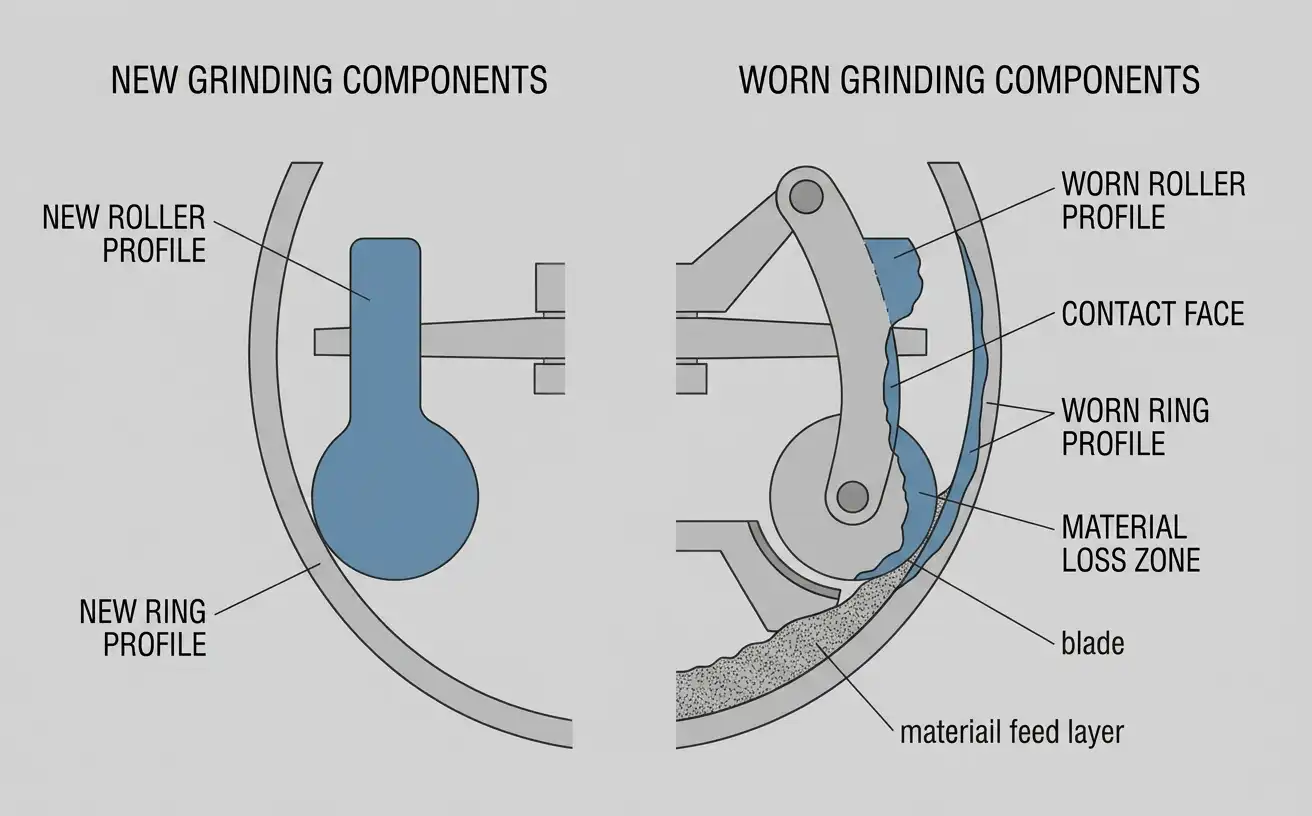
The grinding roller and grinding ring are the primary wear parts in a Raymond mill, since they are the two surfaces in direct mechanical contact with the abrasive feed material. A 12–13 t/h MGW175 calcium oxide installation documents a configuration addressing two maintenance-relevant failure modes: uneven material buildup causing vibration, and dust adhesion inside pipes and the cyclone collector.
For the vibration failure mode, the documented configuration uses a reinforced cantilever structure for the roller hanger assembly, a high-damping shock-absorbing base under the mill housing, and dynamic balance correction, together with a control system that monitors motor current and vibration in real time and adjusts feed rate to keep the material layer in the grinding chamber stable. For the dust adhesion failure mode, the documented configuration uses mirror-polished interior pipe walls, an anti-clogging tapping or automatic pneumatic hammer cleaning system on the cyclone collector, and a pulse-jet baghouse using oil-resistant, waterproof, antistatic filter bags.
Grinding roller and ring replacement intervals depend on feed hardness, feed abrasiveness, and operating hours per day, and vary enough across installations that a single hour-based figure would not represent actual field conditions accurately. A wear-life estimate specific to a given feed material and duty cycle is available on request through the manufacturer’s contact form, based on the material characteristics and target capacity for the specific application.
Routine maintenance beyond wear-part replacement includes lubrication of the main shaft bearing (the MGW series uses an internal oil pump, which removes the need for a separate external lubrication station), inspection of the blade and blade base for wear, and periodic cleaning of the air duct system, particularly for feed materials prone to dust adhesion such as calcium oxide and bentonite.
Cost and Procurement
Raymond mill pricing is driven primarily by frame size (which sets roller count, ring diameter, and motor power, as shown in Table 1), followed by classifier type, control system level (manual versus computer-integrated automation), and optional features such as non-stick roller and ring coatings or hydraulic damping systems for high-vibration feed materials. A 15–26 t/h fertilizer grinding installation and a 25–30 t/h calcium oxide grinding installation illustrate two different capacity tiers within the same product series, which is a useful reference point for scoping a comparable inquiry.
Specific unit pricing depends on frame size, optional equipment, freight terms, and destination, and is not published as a fixed list price by manufacturers in this equipment category. A project-specific quotation, including delivered cost and lead time for the applicable frame size and options, is available by submitting feed material and capacity requirements through the manufacturer’s contact form.
Frequently Asked Questions
How does a Raymond mill grind material?
A Raymond mill grinds material by pressing a grinding roller against a fixed grinding ring under centrifugal force generated as the roller hanger swings outward from a rotating spider. Material lifted into the roller-ring gap by a blade is compressed and sheared between the two surfaces, which reduces particle size progressively as it passes through the gap on repeated rotations.
Why is a Raymond mill also called a pendulum mill?
The name refers to the roller hanger, which is pivoted at the top and holds the grinding roller at the bottom, in the same geometric arrangement as a pendulum. As the spider rotates, the roller hanger swings outward from its pivot, exactly as a pendulum swings outward when its pivot point travels in a circular path, which presses the roller against the grinding ring.
What is the difference between a Raymond mill and a ball mill?
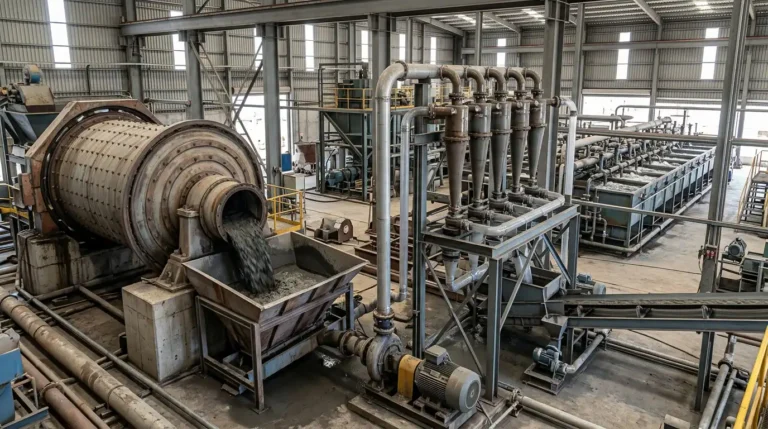
A Raymond mill uses a grinding roller pressed against a grinding ring under centrifugal force, combined with an integrated air classifier, and processes dry feed with moisture content below approximately 6%. A ball mill uses steel grinding media tumbling inside a rotating drum and can process wet feed as a slurry, making it suitable for material or process conditions where dry roller-on-ring grinding does not apply.
What material are Raymond mill grinding rollers and grinding rings made of?
Grinding rollers and grinding rings are commonly cast from high-manganese austenitic steel, covered under specifications such as ASTM A128/A128M, chosen because the material work-hardens at its contact surface under the impact and abrasive load generated during grinding.
What fineness range can a Raymond mill produce?
A standard Raymond mill of the type described in this guide produces a finished powder in the 80 to 400 mesh range (approximately 180 to 38 micrometers), with the achievable throughput decreasing as the target fineness moves toward the finer end of that range.
References & Sources
- ISO 565:1990 — Test sieves — Metal wire cloth, perforated metal plate and electroformed sheet — Nominal sizes of openings
- ASTM A128/A128M-19 — Standard Specification for Steel Castings, Austenitic Manganese
- U.S. Geological Survey, National Minerals Information Center — Barite Statistics and Information
- Coperion — Raymond® Fine Grinding Roller Mill
- Schenck Process — Raymond® Roller Mills: Technical Specifications and Capacity Data
- Occupational Safety and Health Administration — 29 CFR 1910.1053, Respirable Crystalline Silica